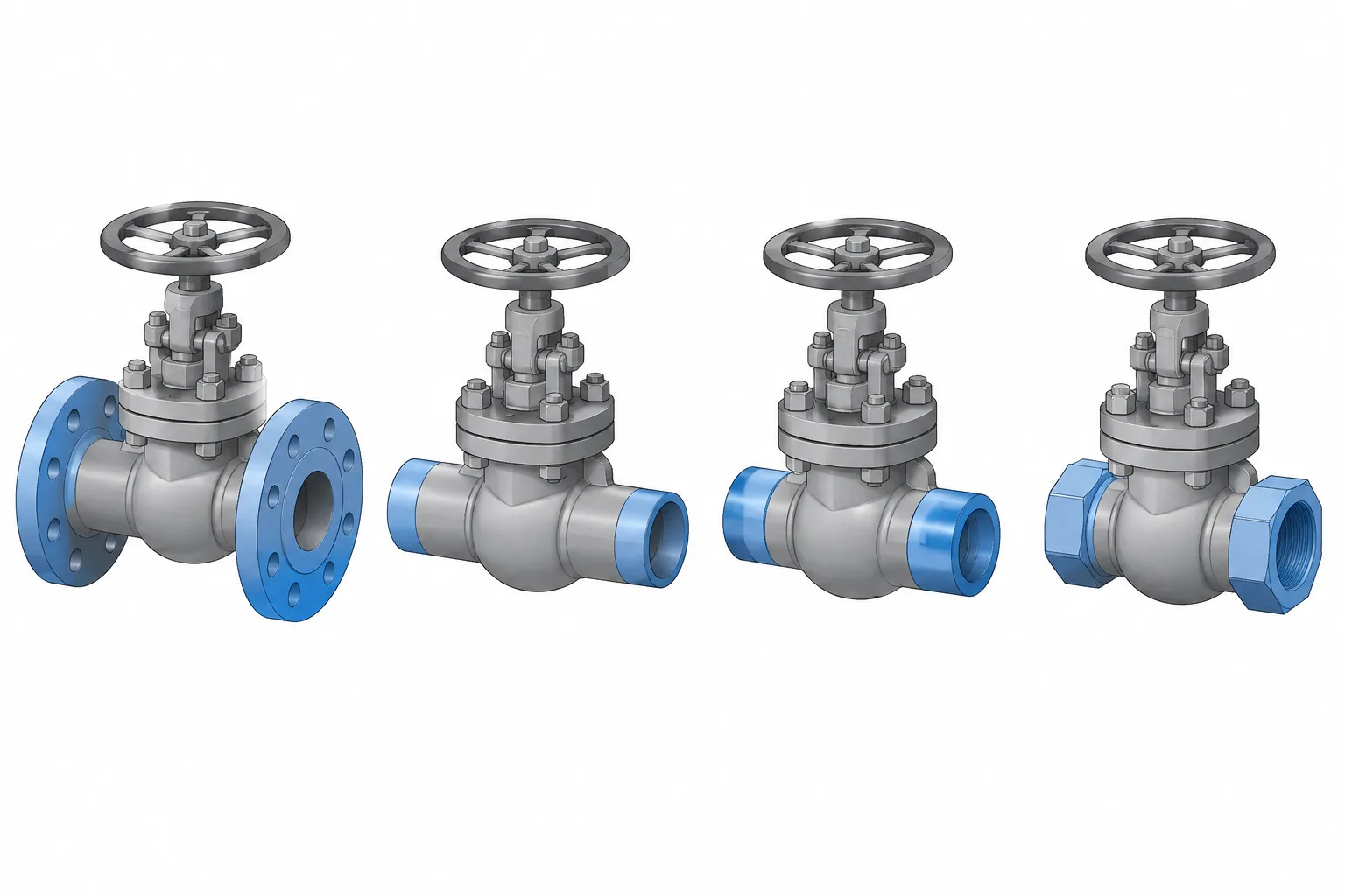
Valve end connections in piping CAD must be treated as functional interfaces, not cosmetic variations of the same component. Each connection method establishes different reference points for placement, pipe cut-length control, adjoining parts, fabrication, and future disassembly.
This guide compares flanged, butt-weld, socket-weld, and threaded valve ends from a practical modeling perspective. It is intended to help designers and drafters coordinate valve geometry with piping specifications, component data, isometrics, material records, construction access, and maintenance planning.
A valve body may perform the same process function with several different end-connection options, but those options are not interchangeable in a piping layout. Flanged, butt-weld, socket-weld, and threaded ends create different joint geometry, dimensional controls, installation requirements, and maintenance constraints.
For a piping designer or CAD drafter, selecting the correct valve symbol or approximate body shape is not enough. The model must represent how the valve actually connects to the line. That choice affects mating components, pipe cut lengths, weld locations, bolting access, insulation envelopes, and the ability to remove the valve later.
What a valve end connection controls
The end connection is the interface between the valve and the adjoining pipe, flange, fitting, or connector. It influences several parts of the design:
- The valve’s end-to-end or face-to-face dimension
- The required mating components on each side
- The number and type of field or shop joints
- Pipe cut-length calculations
- Access needed for welding, bolting, inspection, or disassembly
- Material class and pressure-temperature compatibility
- The model envelope around hubs, flanges, bolts, and operators
A valve should therefore be modeled from verified dimensional data for its exact size, type, end configuration, and applicable specification. A generic valve block may be useful during an early routing study, but it should not silently become fabrication geometry.
Comparison of common valve end types
| End type | Typical CAD interface | Primary dimensional concern | Maintenance implication |
|---|---|---|---|
| Flanged | Two mating flange faces with gasket and bolting | Face-to-face length and complete joint stack-up | Potentially removable after the joint is unbolted and space is available |
| Butt-weld | Valve weld end aligned directly with pipe or a weld-end component | End-to-end length, bore alignment, and weld-end preparation | Removal normally requires cutting or separating designated welded joints |
| Socket-weld | Pipe inserts into a socket in the valve end | Socket engagement, specified assembly condition, and pipe cut length | Removal generally involves cutting or weld removal |
| Threaded | Male and female tapered or straight threaded interfaces as specified | Thread engagement and makeup position | Disassembly depends on available rotation and the surrounding assembly |
This comparison describes layout behavior rather than selection rules. The project piping specification must determine which end types are permitted for a particular service, size range, material, and design condition.
Flanged valve ends
A flanged valve is installed between mating flanges using gaskets and bolting. In CAD, the valve body alone does not represent the complete installed assembly. The joint also includes the valve flange, gasket region, mating pipe flange, bolts or studs, nuts, and any project-required joint accessories.
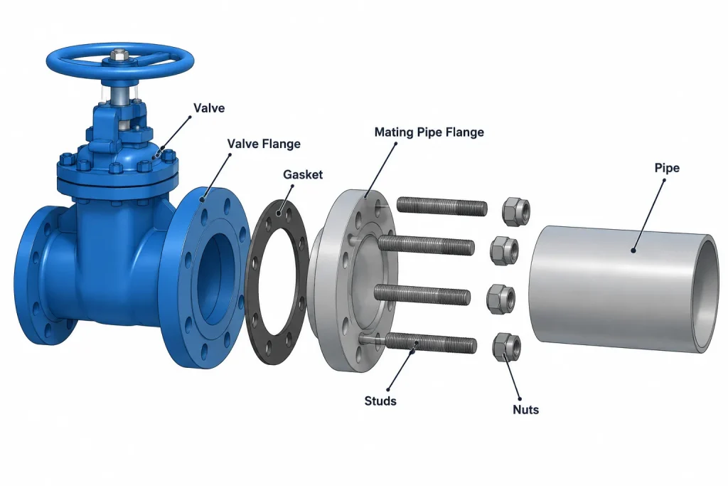
Geometry to model or reserve
- Verified valve face-to-face dimension
- Flange outside diameter and thickness appropriate to the specified connection
- Raised, flat, ring-joint, or other required facing geometry when relevant to the model purpose
- Bolt and nut access envelope
- Space for flange separation and valve withdrawal
The visible gap between modeled flange solids should not be treated as an arbitrary drafting space. Gasket representation and the flange-face reference used by the component data must be consistent throughout the model. Otherwise, small errors can accumulate across a run containing several flanged components.
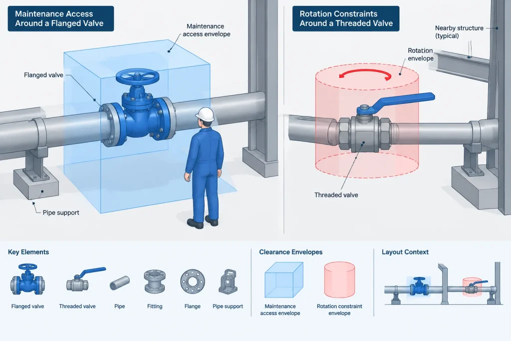
Flanged ends can support removal without cutting the pipe, but removability is not automatic. The layout still needs enough movement to separate the faces, clear studs where applicable, and lift or slide the valve around nearby piping, steel, cable tray, or equipment.
Butt-weld valve ends
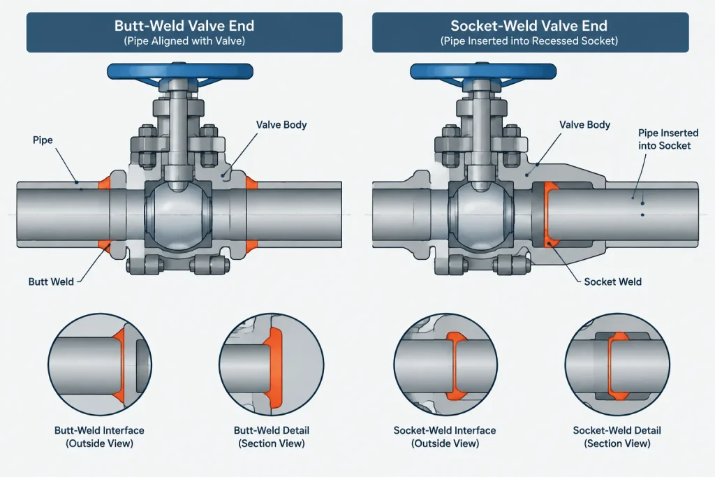
A butt-weld valve connects directly to compatible weld ends. This can produce a compact, continuous piping assembly without separate mating flanges. The critical CAD dimension is generally the valve end-to-end length between defined weld-end reference points.
The designer should not assume that every butt-weld valve end matches the adjoining pipe bore without review. Valve end geometry can depend on the ordered product and the specified pipe wall. Bore mismatch, transition details, end preparation, and any required machining must be resolved through the project specification and verified vendor information.
CAD and fabrication considerations
- Place weld points at the actual valve-to-pipe interfaces.
- Use the correct end-to-end dimension instead of reusing a flanged valve body.
- Check whether nearby welds remain accessible for fabrication and examination.
- Identify whether each weld is intended for shop or field completion.
- Plan how the valve could be replaced if cutting is required.
A butt-weld valve should not be represented as a flanged valve with the flanges hidden. The body proportions, end transitions, reference points, and maintenance strategy may all differ.
Socket-weld valve ends
A socket-weld valve receives the pipe end inside a recessed socket, with a fillet weld made around the outside of the connection. Because the pipe enters the valve, its cut length cannot be determined from the valve’s visible outer end alone.
The model or fabrication detail should use verified socket dimensions and the project’s required assembly practice. A drafter should not push the pipe to an assumed internal stop or infer engagement from a simplified catalog image. The insertion condition affects the pipe cut length and the location of the completed joint.
At a low-detail model stage, a socket-weld valve may be represented using ports at controlled connection points. At spool-detail level, the team may need internal socket reference geometry, weld identification, and explicit cut-length logic. The required detail should be agreed upon before quantities or spool dimensions are extracted.
Threaded valve ends
Threaded valve ends connect through specified male and female threads. A simple CAD model often shows the nominal connection plane without modeling individual thread forms. That simplification is usually appropriate for plant layout, but it does not eliminate the need to account for engagement and makeup.
The installed position is not necessarily defined by bringing two visible solid faces into contact. Threaded engagement depends on the specified connection and assembly condition. Modeling a threaded valve by snapping its outer end face to the end of a pipe can therefore produce an incorrect overall length.
Rotation and replacement access
Threaded assembly may require the valve or an adjoining component to rotate. Nearby branches, operators, walls, and equipment can prevent that movement. Unions or another intentional break point may be needed where the assembled run cannot be rotated conveniently. That arrangement must come from the approved piping design rather than being added solely for CAD convenience.
Do not mix connection type with pressure class
Terms describing valve ends and terms describing component ratings answer different questions. “Flanged” describes a connection form; it does not by itself establish the required flange class, facing, material, or compatibility. Likewise, “socket-weld” or “threaded” does not fully define the valve.
A useful valve record normally needs multiple coordinated attributes, such as:
- Valve type and size
- End-connection type
- Applicable rating or class designation
- Body and trim requirements
- Facing or weld-end details where applicable
- Operator type and orientation
- Project tag and piping specification reference
These fields should remain separate in the CAD database. Combining them into an ambiguous description makes component substitution and model checking more difficult.
A practical CAD placement workflow
- Read the piping specification. Confirm the permitted valve type, connection, material requirements, and rating basis.
- Obtain controlled dimensions. Use verified project or manufacturer data for the exact ordered configuration when available.
- Select the correct component family. Do not create a welded-end valve by deleting flanges from a flanged model.
- Place connection ports deliberately. Ports should represent the defined face, weld end, socket reference, or threaded assembly reference.
- Add mating components. Include pipe flanges, gaskets, connectors, or adjoining pipe geometry as required.
- Check the complete assembly. Review cut lengths, weld locations, bolt access, operator clearance, insulation, and removal space.
- Validate extracted data. Confirm that the bill of material and isometric identify the same end type shown in the model.
Common modeling errors
- Using one valve block for every end configuration
- Confusing valve face-to-face dimensions with the length of the full flanged assembly
- Ignoring pipe insertion when calculating socket-weld cut lengths
- Placing threaded components face-to-face without considering engagement
- Assuming matching nominal size guarantees matching weld bores
- Showing a removable flanged valve without providing separation or withdrawal space
- Changing an end type in the model without updating the specification, isometric, and material list
Final review principle
The correct valve model is not simply the one with a recognizable body and operator. It is the one whose connection references, dimensions, mating parts, and metadata describe the intended installed assembly.
When reviewing valve end connections in piping CAD, follow the joint outward: start at the valve body, identify the exact end form, verify the mating component, locate the assembly or weld reference, and then check access for construction and maintenance. This approach catches interface problems that a visual valve-body check can easily miss.
Applying the comparison during model review
A useful valve review should examine both geometry and data. Correct-looking solids can still produce an incorrect installation if the connection ports, end references, component description, or mating parts do not agree.
Geometry review
- Confirm that the valve family represents the specified end configuration.
- Check that each connection point uses the intended face, weld, socket, or threaded reference.
- Review the complete joint rather than checking only the valve body.
- Verify that adjoining pipe and fittings follow the same centerline and bore arrangement required by the design.
- Examine access for bolting, welding, inspection, operation, insulation, and removal.
Data review
- Compare the modeled end type with the piping specification and valve record.
- Confirm that the isometric and material output describe the connection shown in the model.
- Keep connection type, rating designation, material requirements, facing details, and operator information in separate controlled fields.
- Flag provisional geometry so it cannot be mistaken for verified fabrication information.
Managing valve geometry through design development
Early routing models may use simplified valve envelopes, but the connection logic should still be explicit. A placeholder should identify whether its ports represent flange faces, weld ends, socket references, or threaded assembly references. This reduces the risk of preserving an unsuitable placeholder when controlled component data becomes available.
As the model develops, replace assumptions with verified project or manufacturer information. Changes to an end connection should be reviewed as assembly changes because they can affect adjacent components, pipe lengths, joint counts, material output, fabrication planning, and maintenance access.
Frequently asked questions
Can one generic valve model be used for every end connection?
A generic envelope may support preliminary routing, but it should not be treated as final component geometry. Flanged, butt-weld, socket-weld, and threaded valves can use different connection references, body transitions, installed lengths, and mating components.
What is the main CAD reference for a flanged valve?
The model should use the defined flange-face references and the verified valve face-to-face dimension. The complete installed joint must also account for mating flanges, the gasket region, bolting, and required access.
Why does a socket-weld valve affect pipe cut length?
The pipe enters the valve socket, so the visible end of the valve is not necessarily the pipe termination reference. Cut-length logic must follow verified socket geometry and the required assembly practice.
Should individual threads be modeled on a threaded valve?
Detailed thread forms are often unnecessary for plant-layout models. The important requirement is a controlled connection reference that represents the intended engagement and makeup condition rather than an arbitrary visible face.
Does a flanged connection guarantee that a valve can be removed easily?
No. Removal also requires room to separate the joint, handle the bolting, and move the valve clear of nearby piping, structures, equipment, insulation, and other obstructions.
Can a butt-weld valve be created by removing flanges from a flanged model?
No. That edit does not establish the correct weld-end references, end transitions, verified length, bore relationship, or component metadata. The proper welded-end component family and controlled data should be used.
Who determines which valve end type is permitted?
The project piping specification and approved component requirements govern selection. CAD geometry should represent that decision rather than independently determining the connection type.