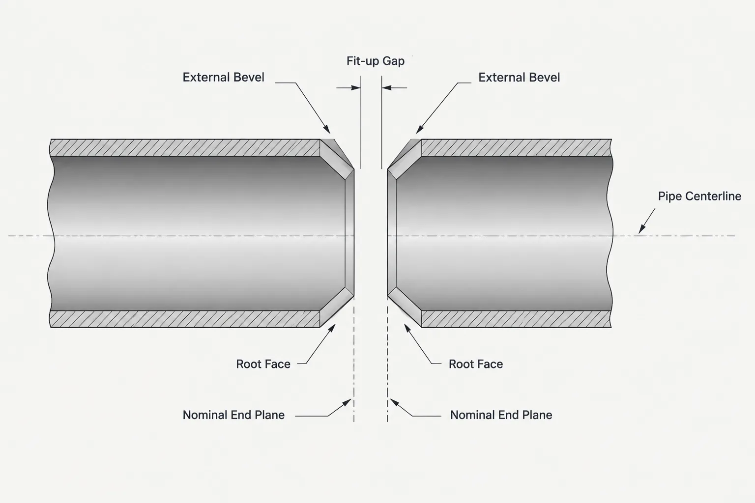
Butt-weld end preparation sits at the boundary between piping design, CAD administration, and fabrication. A model may connect components correctly while omitting the physical bevel, root face, and fit-up separation needed to make the joint. That simplification is not inherently wrong, but the project must clearly define what each modeled endpoint represents.
This guide explains how to distinguish nominal connection geometry from fabrication-controlled joint details. It also shows where end preparation can influence cut-length calculations, bore alignment, spool documentation, field work, and the review of special interfaces.
Butt-welded piping components are often modeled as if two simple end planes meet. That representation is efficient for routing and layout, but it does not describe everything the fabricator must control at the joint. The physical ends may include bevels, root faces, internal transitions, special machining, and a fit-up gap established by the applicable welding procedure.
Understanding the difference between nominal CAD geometry and fabrication end preparation helps prevent misleading cut lengths, incorrect weld details, and false assumptions about how components will fit together. The goal is not to model every weld groove in every piping model. It is to identify which information belongs in the model, which belongs in drawings or specifications, and which must come from an approved fabrication procedure.
What Is Butt-Weld End Preparation?
Butt-weld end preparation is the shaping and conditioning of component ends before they are joined by welding. A prepared end may include an external bevel, a short root face at the bore, an internal taper, or another joint-specific profile. Preparation also includes practical matters such as cleaning, alignment, and establishing the required separation between the ends.
The prepared profile is not determined by pipe size alone. It can depend on wall thickness, component type, material, bore mismatch, welding process, project specification, and the qualified welding procedure. Consequently, a generic CAD library should not treat one detailed bevel profile as universally applicable.
Common Joint Terms
| Term | Practical meaning | CAD significance |
|---|---|---|
| Bevel | An angled surface machined or formed at the component end to provide access for welding. | Often omitted from layout models but may be shown in fabrication details. |
| Root face | The small un-beveled land near the inside edge of a prepared end. | Should not be inferred from a schematic bevel symbol or generic model. |
| Root opening | The intended separation between opposing prepared ends during fit-up. | May affect fabrication cut lengths and assembly dimensions if the workflow accounts for it explicitly. |
| Groove | The space formed by the prepared ends that receives weld metal. | Its shape is normally governed by welding documentation rather than piping layout geometry. |
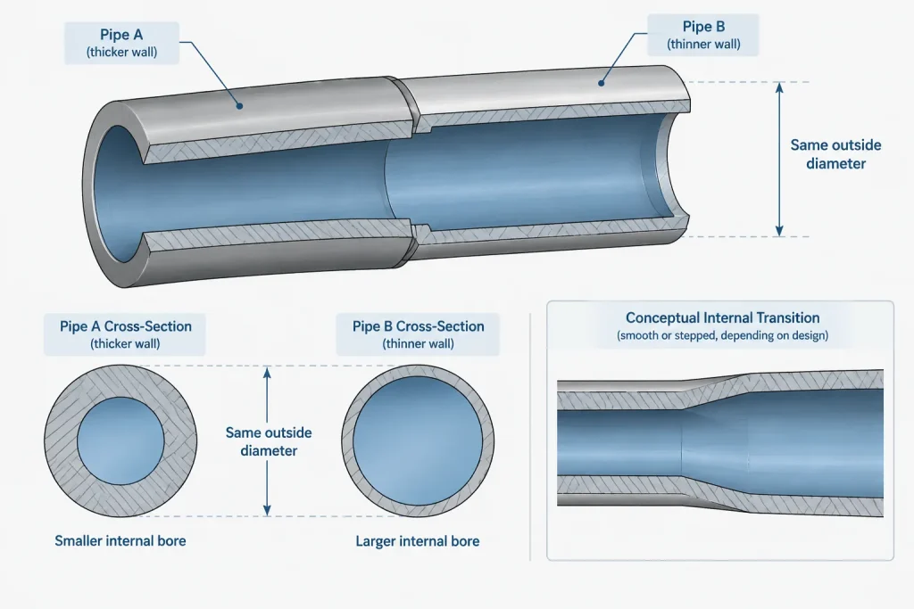
| Internal transition | A tapered or contoured change used where adjoining bores or wall thicknesses differ. | May require a component-specific detail and cannot always be represented by a standard pipe solid. |
| Hi-lo | Informal shop terminology for internal misalignment between adjoining bores. | A perfect CAD centerline connection does not prove acceptable internal alignment. |
The Component End Plane Is Not Always the Weld Centerline
A frequent modeling mistake is to use the words end plane, weld point, and weld centerline as though they describe the same location. They may coincide in a simplified model, but they represent different concepts.
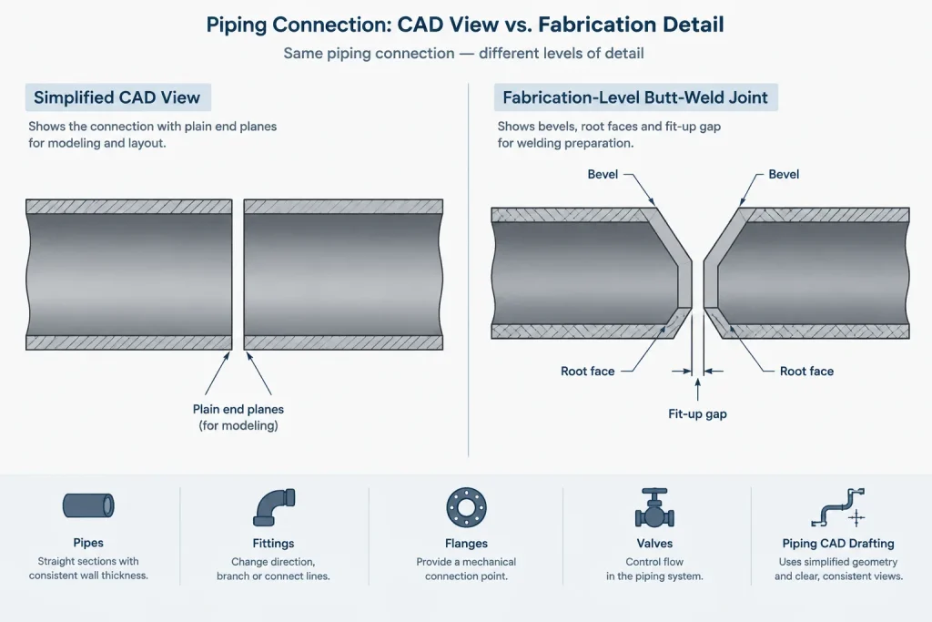
- Component end plane: The nominal terminal plane used to define the overall length of a pipe, fitting, flange, or valve end.
- Fit-up plane: The physical prepared end surface positioned for assembly.
- Joint gap: The separation established between the prepared ends where required by the fabrication procedure.
- Weld reference location: The point or line used by the project to identify the joint on an isometric, weld map, or fabrication record.
If two CAD ports snap directly together, the software may place both component end planes at one coordinate. That is useful for connectivity, but it can visually eliminate the physical fit-up gap. Alternatively, a modeling system may incorporate a nominal gap into cut-length calculations. The project must know which convention is being used; mixing the two methods can create cumulative length errors.
Why a Simplified Model Is Often Appropriate
Detailed bevel geometry adds faces, edges, and data without necessarily improving plant layout. For routing, clash detection, support coordination, and general arrangement drawings, the important features are usually the pipe outside envelope, component end location, centerline, bore continuity, and accessible space.
A simplified butt-weld connection is generally useful when:
- The model supports arrangement rather than weld fabrication.
- Cut lengths are derived using a separate fabrication rule or shop workflow.
- End preparation is controlled by project specifications and welding procedures.
- The joint has no unusual bore transition or special machining.
- Drawings clearly distinguish nominal component geometry from fabrication detail.
Simplification becomes risky when users assume the model contains details that were never represented. Model documentation should state whether component ports represent nominal ends, prepared ends, joint centers, or another project-defined reference.
When End Preparation Needs Explicit Documentation
Some joints require more information than a standard butt-weld symbol and connected centerlines can provide. These conditions should be identified for engineering and fabrication review rather than resolved by an unverified generic CAD detail.
Dissimilar Wall Thicknesses
Pipe and components with the same nominal size can have different bores because their wall thicknesses differ. Aligning their outside diameters in CAD may therefore produce an internal step. Whether an internal transition is required, and how it should be formed, depends on the controlling design and fabrication requirements.
Dissimilar Outside Diameters
Nominally connected items may not share the same actual outside diameter, particularly at equipment, specialty items, fabricated transitions, or nonstandard components. The model should show the verified interface rather than forcing two generic ports to match.
Special Weld Profiles
Heavy-wall joints, single-side access, corrosion-resistant overlays, liners, or project-specific welding arrangements may use end profiles that differ from a basic external bevel. These should be shown in a controlled detail or referenced fabrication document.
Field-Prepared Ends
A field-cut pipe may be delivered long and trimmed during installation. In that case, the design model may control the final joint location while the field procedure controls cutting and end preparation. The drawing should avoid implying that a shop-prepared final end already exists if that is not the intended construction sequence.
Cut Length and Root Opening
For a straight pipe piece installed between two butt-weld components, a theoretical face-to-face distance is not automatically the pipe cut length. The result depends on what the referenced faces represent and how the project handles joint gaps, fitting takeoffs, field trim, and fabrication allowances.
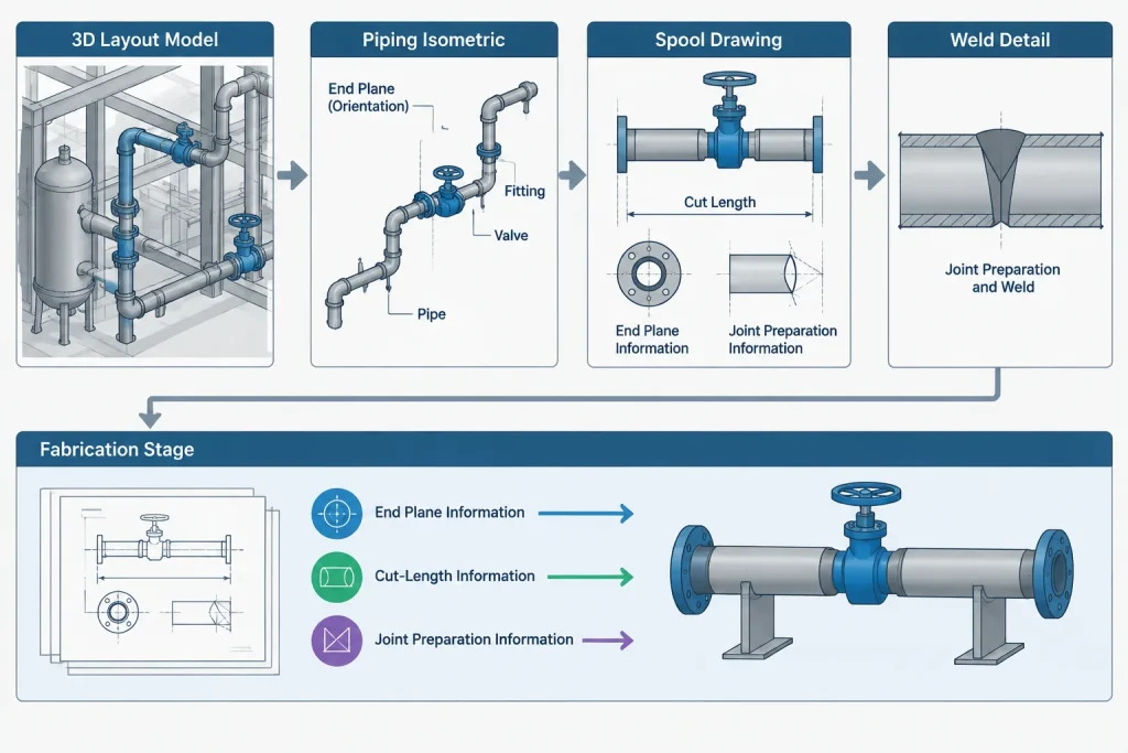
A reliable workflow starts by defining:
- The coordinates or reference planes that control the completed assembly.
- Whether fitting dimensions terminate at nominal component ends.
- Whether the model displays or suppresses fit-up gaps.
- Whether cut length output applies a joint allowance automatically.
- Whether any end will be trimmed or prepared in the field.
The same allowance must not be applied twice—once through modeled separation and again through a fabrication calculation. It must also not be omitted because users assumed that a visible CAD seam represented a physical gap.
Recommended CAD and Drawing Workflow
- Use verified component dimensions. Build or select fittings using the applicable dimensional source and project specification. Do not derive a fitting by scaling another nominal size.
- Define the port convention. Document whether a butt-weld port is located at the nominal end plane, joint center, or another reference.
- Model the required envelope. Include outside geometry needed for layout and clashes. Add internal geometry only when it supports a real checking requirement.
- Flag mismatched bores. Compare adjoining component data where wall thickness, specialty construction, or equipment interfaces create uncertainty.
- Separate layout from weld design. Do not let a generic bevel in a CAD block substitute for an approved joint preparation or welding procedure.
- Control special details. Reference a project detail, spool note, or fabrication instruction when machining or transition geometry is joint-specific.
- Check cut-length logic. Confirm how the fabrication system treats end planes, root openings, and field allowances before releasing spool information.
- Preserve revision traceability. If an end preparation changes, review related cut lists, spool drawings, weld maps, material records, and inspection documents.
What to Show on Different Deliverables
| Deliverable | Typical useful information | Information usually controlled elsewhere |
|---|---|---|
| Piping model | Centerline, outside envelope, nominal ends, connectivity, component identity | Detailed weld groove and procedure variables |
| General arrangement | Overall location, orientation, access, interfaces | Shop end machining |
| Isometric | Joint location, dimensions, weld identification, field or shop status | Full joint-preparation geometry unless specially detailed |
| Spool drawing | Piece lengths, joint numbers, component ends, special fabrication notes | Procedure-specific welding instructions unless referenced |
| Weld detail | Required joint profile, transitions, backing arrangement where applicable | Plant-wide layout information |
Practical Review Questions
Before releasing a butt-welded assembly, reviewers should ask:
- What physical location does each CAD port represent?
- Does the cut-length method account for the project’s joint-gap convention?
- Are the adjoining bores and wall selections compatible?
- Is any internal taper, counterbore, or special machining required?
- Is the joint intended for shop welding or field welding?
- Does the drawing distinguish a nominal model seam from an actual prepared joint?
- Are special requirements tied to a controlled specification or fabrication detail?
Butt-weld end preparation is a fabrication-controlled subject that intersects directly with CAD geometry. A sound model establishes location, connectivity, and usable component dimensions without pretending to define an unverified weld profile. Clear port conventions, explicit cut-length rules, and controlled special details allow the model and the fabrication process to serve their respective purposes without contradiction.
Managing End-Preparation Information Across the Workflow
The most reliable workflow assigns each type of information to a controlled source. The piping model should establish component identity, routing, connectivity, and the reference geometry needed for layout. Drawings should communicate joint locations, piece limits, fabrication status, and any special instructions that affect the assembly. The approved fabrication documentation should control the actual groove profile, fit-up requirements, and welding-related preparation.
Problems arise when those sources silently overlap. A detailed bevel modeled for appearance may be mistaken for an approved fabrication requirement. A visible seam may be interpreted as a physical root opening even though both CAD ports occupy the same coordinate. Conversely, a fabrication system may apply a joint allowance that has already been represented in the model.
Useful Model Metadata
Where the CAD platform supports component or connection attributes, project teams can record the meaning of a butt-weld port without adding unnecessary solid geometry. Useful metadata may identify:
- Whether the port marks a nominal component end or another project-defined reference.
- Whether the connection is intended for shop or field assembly.
- Whether a special end-preparation detail applies.
- Whether adjoining bore data require review.
- Whether cut-length processing handles the fit-up allowance outside the model.
Metadata should support coordination rather than replace controlled specifications, approved procedures, or fabrication details. Attribute names and permitted values should be standardized within the project so that designers, drawing producers, and fabrication-data users interpret them consistently.
Interface Review Before Fabrication Release
A focused interface review is especially useful where standard pipe connects to equipment, specialty components, fabricated items, or components with different wall selections. The reviewer should compare the actual connection data rather than relying only on matching centerlines or nominal descriptions.
The review should establish which geometry controls the completed assembly, whether an internal discontinuity exists, who is responsible for any transition or machining, and how the resulting instruction will appear in the fabrication package. If those questions cannot be answered from controlled project information, the joint should be flagged instead of completed with an assumed generic bevel.
Revision and Change Control
An end-preparation change can affect more than the weld detail. Depending on the project workflow, it may also affect piece lengths, interface geometry, spool notes, joint identification, inspection planning, and field instructions. Revisions should therefore be checked across the model, drawings, cut data, and fabrication records rather than treated as an isolated drafting edit.
Frequently Asked Questions
Should every butt-weld bevel be modeled in piping CAD?
No. Detailed bevel geometry is often unnecessary for routing, arrangement, and clash review. It should be modeled only when it supports a defined checking or fabrication purpose and is based on controlled project information.
Is the root opening the same as the bevel?
No. The bevel is the prepared angled surface at an end. The root opening is the intended separation between opposing prepared ends during fit-up. They are related features but must not be treated as interchangeable.
Does a CAD connection seam prove that a physical fit-up gap exists?
No. A seam may simply mark the coincident end planes of connected components. The project’s port convention and cut-length method determine whether a physical gap is represented, calculated elsewhere, or suppressed from the model.
Can a generic CAD bevel define the fabrication requirement?
A generic bevel can illustrate the concept, but it should not substitute for the approved joint detail or fabrication procedure. End preparation can vary with the connected components, material, wall selection, welding process, access, and project requirements.
Why can matching nominal pipe sizes still have a bore mismatch?
Nominal size does not by itself establish identical internal geometry. Different wall selections or component constructions can produce different bores, even when the nominal connection descriptions match.
How can fit-up gaps create cut-length errors?
Errors occur when a gap allowance is applied twice or omitted entirely. The cut-length workflow must state whether the separation is included in modeled geometry, introduced by fabrication calculations, or handled through another controlled method.
What should be done when the required end preparation is uncertain?
Flag the connection for engineering or fabrication review. Do not infer a joint profile from a schematic weld mark, an unrelated CAD component, or a visually similar connection.