Category: How To

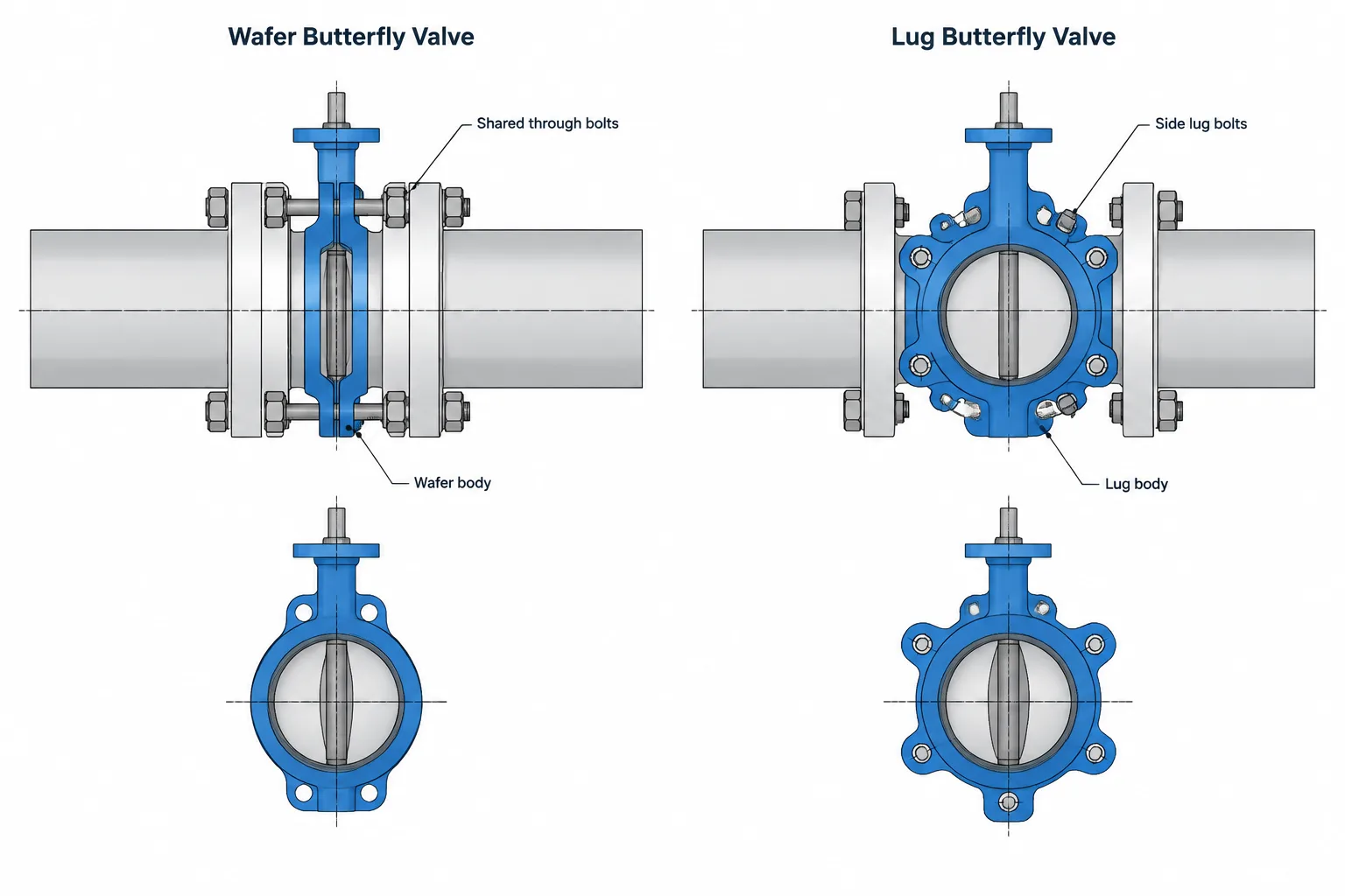
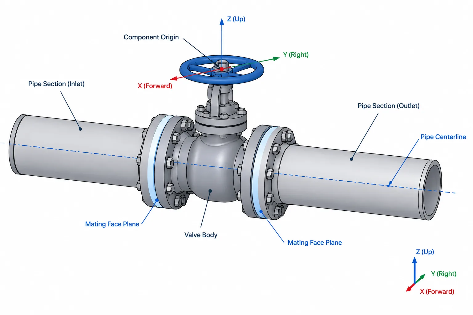
  • Valve End Connections in Piping CAD: Flanged, Butt-Weld, Socket-Weld, and Threaded

    Valve End Connections in Piping CAD: Flanged, Butt-Weld, Socket-Weld, and Threaded

  • Flange Facing Finish in Piping Drawings: Serrations, Roughness, and Gasket Compatibility

    Flange Facing Finish in Piping Drawings: Serrations, Roughness, and Gasket Compatibility

  • Pipe Elevation Notation in CAD: Centerline, BOP, TOP, and Invert Explained

    Pipe Elevation Notation in CAD: Centerline, BOP, TOP, and Invert Explained

  • Equipment Nozzle Projection in Piping CAD: Reference Points, Flange Faces, and Interface Control

    Equipment Nozzle Projection in Piping CAD: Reference Points, Flange Faces, and Interface Control

  • Dead Legs in Piping Layout: How to Identify, Measure, and Document Stagnant Branches

    Dead Legs in Piping Layout: How to Identify, Measure, and Document Stagnant Branches

  • Piping CAD Revision Control: How to Track Model, Drawing, and Data Changes

    Piping CAD Revision Control: How to Track Model, Drawing, and Data Changes

  • Long-Radius vs. Short-Radius Elbows: Space, Flow, and CAD Layout Considerations

    Long-Radius vs. Short-Radius Elbows: Space, Flow, and CAD Layout Considerations

  • Standard Dimensions vs. Manufacturer Dimensions in Piping CAD: What Can Be Treated as Generic?

    Standard Dimensions vs. Manufacturer Dimensions in Piping CAD: What Can Be Treated as Generic?

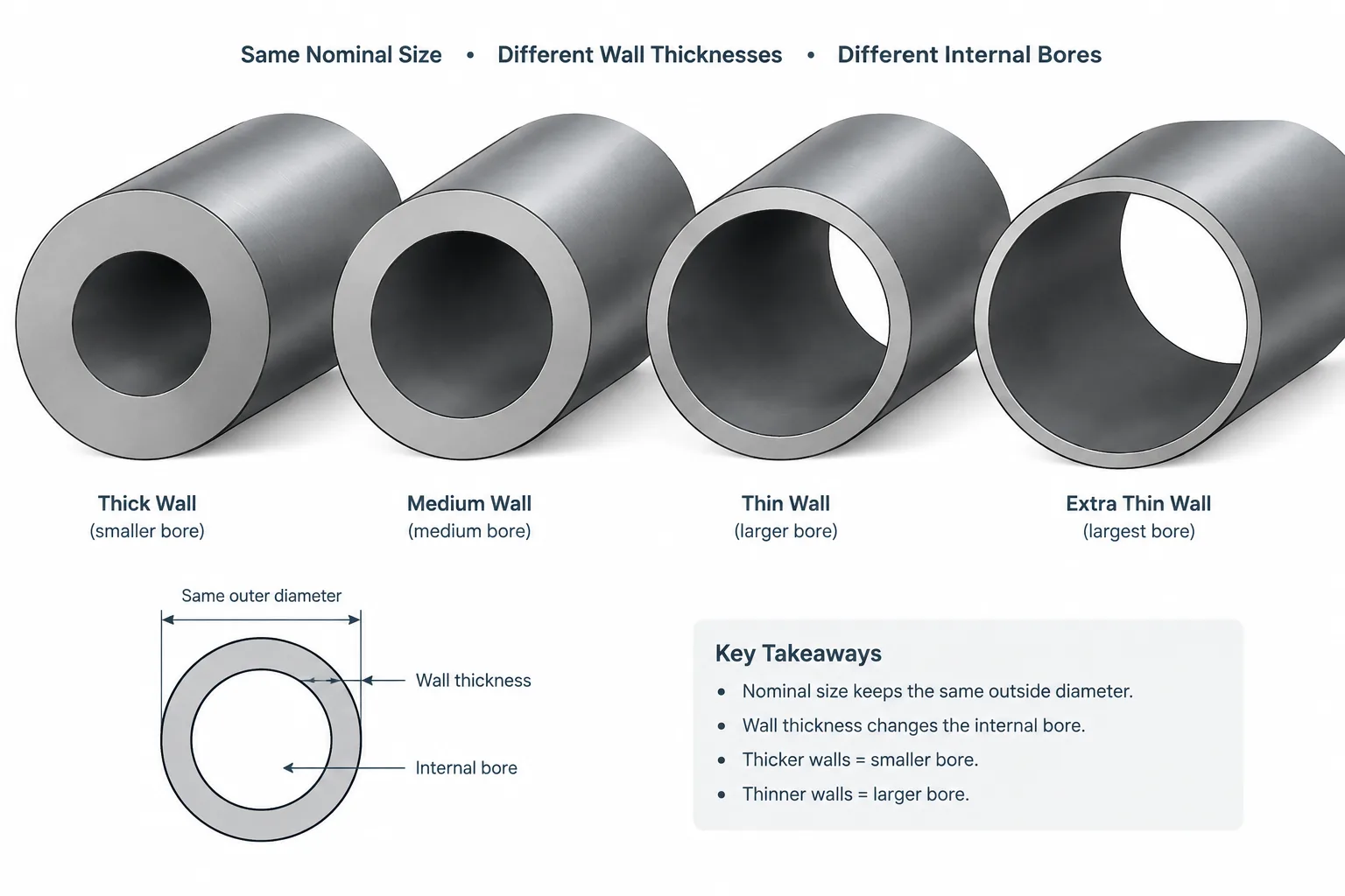
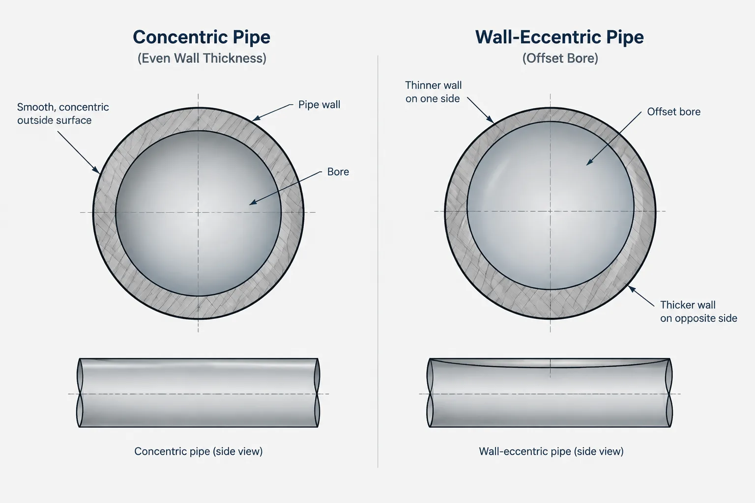
  • Corrosion Allowance in Piping: How It Relates to Pipe Schedule, Wall Thickness, and CAD

    Corrosion Allowance in Piping: How It Relates to Pipe Schedule, Wall Thickness, and CAD