
Instrument connections in CAD require more than placing an instrument symbol beside a process line. The drawing must show how the connection begins, which components belong to the assembly, and how the arrangement fits into the surrounding plant.
This guide explains a practical workflow for detailing pressure taps, impulse lines, sample points, vents, drains, thermowells, manifolds, and other small-bore connections. It focuses on traceability, legibility, physical coordination, and disciplined use of project source documents.
Instrument connections and small-bore piping are easy to overlook in a large piping model. They may occupy little drawing space, but they often carry important information about measurement, isolation, draining, venting, access, and connection type. A main line can look complete while a pressure tap, sample connection, impulse line, or instrument valve arrangement remains unclear.
Good CAD detailing makes these connections understandable without turning the drawing into a crowded collection of tiny symbols. The goal is to preserve the process connection, show the physical routing that matters, and provide enough information for design review, fabrication, installation, and maintenance coordination.
What counts as an instrument connection?
An instrument connection is the physical interface between a process line or equipment item and an instrument or measurement system. It can include the process takeoff, a root isolation valve, a short small-bore assembly, tubing or pipe, a manifold, and the instrument itself. The exact arrangement depends on the instrument service and the project’s piping and instrumentation requirements.
Common examples include:
- Pressure and differential-pressure instrument connections
- Temperature element connections and thermowell assemblies
- Flow measurement connections
- Level instrument connections at vessels and tanks
- Sample, analyzer, vent, and drain connections
- Utility connections for instrument air or other services
- Small-bore bypasses, equalizing lines, and local gauge assemblies
The process diagram may define the functional relationship, while the piping CAD model or detail drawing must show how the connection exists in physical space. These are related but different tasks. A schematic symbol does not automatically define the final orientation, elevation, valve position, support arrangement, or access path.
Start with the source information
Before drawing a small-bore connection, collect the information that controls its arrangement. The primary sources commonly include the P&ID, piping material specification, instrument index, instrument data sheet, line list, equipment drawings, and project drafting conventions.
Check each source for a different type of requirement:
| Source | What to verify |
|---|---|
| P&ID | Instrument tag, process function, isolation intent, vents, drains, bypasses, and connection relationships |
| Piping material specification | Permitted materials, valves, fittings, branch components, end connections, and joining requirements |
| Instrument data sheet | Instrument connection information, orientation needs, process limits, and manufacturer interface details |
| Equipment drawing | Nozzle location, available connection points, access restrictions, and equipment orientation |
| CAD standards | Layer use, line weights, symbols, tags, annotation style, and representation rules |
Do not infer a connection type merely from the instrument symbol. If the source documents disagree, record the discrepancy and obtain clarification through the project review process. Changing a connection in CAD without resolving the underlying design information can create a drawing that appears complete but does not represent the intended system.

Separate the process connection from the instrument
A clear drawing distinguishes the process-side connection from the instrument-side device. This helps reviewers follow the pressure boundary and understand where isolation or maintenance separation occurs.
At a minimum, the detail should make these elements identifiable when they apply:
- The main pipe, vessel, or equipment connection point
- The branch or fitting used to create the takeoff
- The first isolation or root valve
- Small-bore pipe or tubing between components
- Manifolds, needle valves, check valves, filters, or other inline items
- The instrument tag and instrument symbol
- Any required vent, drain, test, or equalizing connection
Not every project requires every component to be drawn at the same level of detail. However, the representation should be consistent with the drawing purpose. A piping isometric may use a simplified instrument symbol and a reference to a separate instrument detail. A fabrication or installation detail may need a more complete arrangement, including fitting orientation and connection notes.
Choose the right CAD representation
Small-bore items are often difficult to show at the same scale as process piping. Use a representation that remains legible at the intended plot size. A centerline, single-line symbol, or schematic-style detail may be appropriate for a general arrangement, while a spool or fabrication drawing may require geometry that distinguishes pipe, tubing, fittings, and valves.
Useful representation practices include:
- Use approved symbols for instrument valves, manifolds, thermowells, and specialty fittings.
- Keep process piping and instrument tubing visually distinguishable where project conventions require it.
- Use a detail callout when the connection cannot be read clearly in the main view.
- Show breaks in insulation or cladding when they affect instrument access or installation.
- Use leaders that terminate on the intended component rather than crossing several nearby lines.
- Keep instrument tags readable and consistent with the source documents.
Avoid using a generic block that hides connection orientation. A block may be useful for a repeated instrument assembly, but its insertion point, connection ports, rotation behavior, and attribute fields should be tested before the block enters the production library.
Check orientation, access, and routing
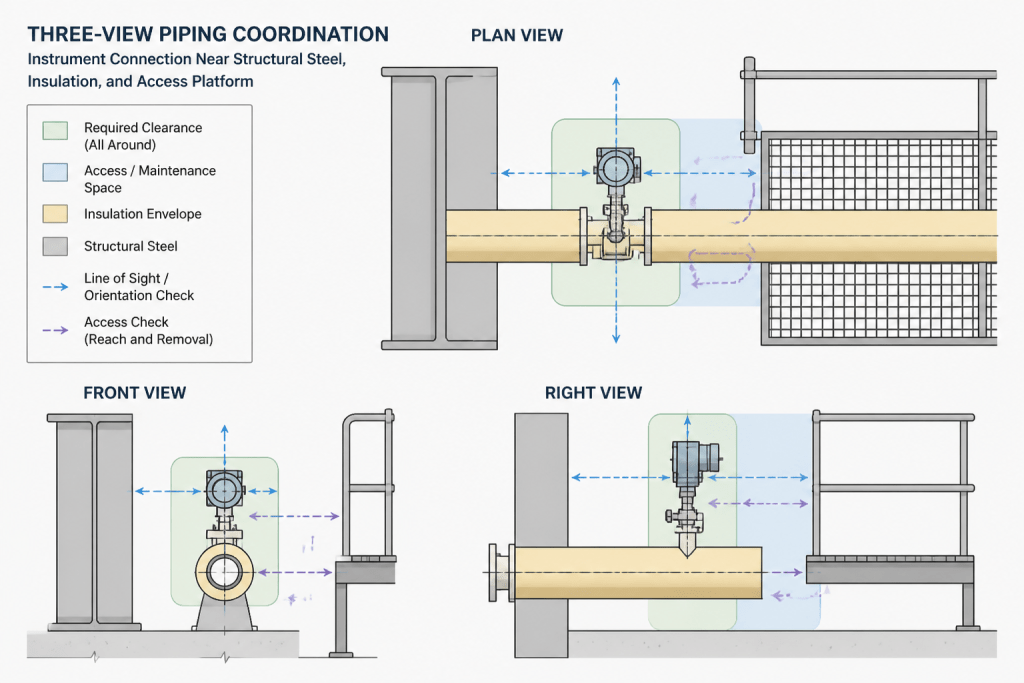
Instrument connections must be reviewed in the same physical context as the surrounding piping. An arrangement that looks acceptable in an isometric may be inaccessible when viewed against structural steel, platforms, insulation, cable tray, or adjacent equipment.
Review the following questions:
- Can the instrument be identified and reached from an intended operating or maintenance location?
- Is the isolation valve oriented so that its handle or actuator is not blocked?
- Does the connection avoid collisions with supports, steel, ladders, platforms, and adjacent lines?
- Does the routing preserve the intended high-point or low-point behavior where the service requires it?
- Are tubing bends, fittings, and manifolds represented without implying an impossible installation?
- Does the instrument remain connected after insulation, removable covers, or equipment movement are considered?
These checks are coordination checks, not a substitute for process, instrumentation, mechanical, or operations review. CAD can reveal a spatial conflict, but the responsible discipline must decide whether a revised orientation or routing satisfies the design intent.
Pay attention to branch details
A small-bore connection usually begins at a branch, nozzle, or dedicated instrument port. The drawing should show where the branch occurs and how it relates to the pipe wall or equipment boundary. Use the component type required by the piping specification rather than selecting a convenient generic fitting.
Branch representation should answer three practical questions:
- Where does the connection originate?
- What components are installed immediately downstream of the origin?
- How does the connection transition to the instrument or tubing system?
When the branch is too small to read in the main view, use a keyed detail, enlarged plan, or connection schedule. Keep the identifier consistent across the model, drawing, and bill of materials. Do not duplicate or omit a branch component simply because it is visually small.
Use a focused review workflow
A repeatable review process reduces missed connections. Start by filtering the model or drawing set for instrument tags and small-bore components. Then trace each connection from the instrument back to the process source.
- List the connections: Compare the P&ID, instrument index, and model to identify missing or extra instruments.
- Trace the path: Follow each connection from the process boundary through valves, fittings, tubing, and the instrument.
- Check specifications: Confirm that visible components match the assigned piping or instrument material requirements.
- Review orientation: Inspect plans, elevations, and isometrics for access and interference issues.
- Verify annotation: Check tags, callouts, line numbers, valve identifiers, and detail references.
- Compare revisions: Confirm that changed instruments or connection arrangements are reflected in all affected views.
A connection checklist can be especially useful during model reviews because small-bore details are often distributed across several drawings. Record the review status by instrument tag or connection identifier rather than relying only on a general drawing mark-up.
Common CAD mistakes to avoid
- Using a symbol without a physical connection: An instrument symbol placed near a line does not prove that it is connected.
- Drawing every assembly identically: Repeated blocks can conceal differences in valve count, orientation, or connection type.
- Leaving the branch ambiguous: A leader that ends near a pipe can make the source point uncertain.
- Ignoring scale and plot size: Fine geometry may disappear when the drawing is printed or exported.
- Forgetting insulation and access: The instrument may be spatially present but operationally blocked.
- Changing the design while drafting: A drafter should document conflicts rather than silently altering process intent.
Final drawing check
A well-detailed instrument connection allows a reviewer to answer four questions quickly: what is being measured, where the process connection originates, what components separate or condition the connection, and how the instrument can be accessed. The best CAD workflow combines source-document verification, consistent symbols, readable annotation, and three-dimensional coordination.
Use reference tables and component databases for verified dimensions and connection data, but keep those values tied to the applicable specification and project requirements. The CAD drawing should communicate the selected arrangement clearly; it should not be used to guess missing design information.
Why small-bore detailing deserves a focused review
Small-bore piping can have a disproportionate effect on constructability and maintenance. Its geometry may be visually minor, but the connection can determine whether an instrument is isolated, drained, vented, tested, reached, and replaced as intended.
The most useful way to review these details is to connect three views of the same design:
- Functional view: the P&ID and instrument documents explain what the connection is intended to do.
- Physical view: the CAD model and drawings show where the connection is located, routed, oriented, and supported.
- Specification view: piping, valve, instrument, and drafting requirements define which components and representations are permitted.
Keeping these views aligned helps prevent a common drafting problem: a connection that looks complete in one drawing but cannot be traced, accessed, or coordinated in the physical model.
How to use this page during design review
Use the source-document section before modeling, the representation guidance while preparing views and blocks, and the review workflow when checking the completed drawing set. For difficult arrangements, review the connection in more than one view and use an enlarged detail rather than compressing important information into a crowded general view.
When a required detail is missing or conflicting, preserve the discrepancy for resolution. CAD should communicate the approved design intent; it should not silently decide an unresolved connection type, valve arrangement, routing requirement, or instrument orientation.
Relationship to piping reference data
Dimensions, end connections, fitting selections, and component data should come from the applicable project specification and verified reference resources. The drawing workflow described here explains how to communicate and coordinate those selections, not how to substitute guessed values for missing design information.
Frequently asked questions
What should an instrument connection detail show?
It should identify the process or equipment connection point, the branch or takeoff, applicable isolation and inline components, the small-bore route, the instrument, and any required vent, drain, test, or equalizing connection.
Should the instrument be drawn as a full physical assembly?
That depends on the drawing purpose. A general arrangement may use approved symbols and a detail reference, while a fabrication or installation drawing may need clearer geometry for fittings, valves, tubing, orientation, and access.
Why is a nearby instrument symbol not enough?
A symbol placed near a pipe does not establish a physical connection. The branch origin, intervening components, route, and instrument interface must be identifiable and traceable.
How should conflicting source documents be handled?
Record the discrepancy and route it through the project review process. Do not change the CAD arrangement silently, because the apparent drafting correction may alter the intended process or instrument design.
What should be checked after the connection is modeled?
Trace the connection from the instrument to the process boundary, compare it with the source documents, verify component requirements, review access and interference, and check tags, callouts, identifiers, and affected revisions.
When is an enlarged detail useful?
An enlarged detail is useful when the branch, valve arrangement, tubing route, connection orientation, or annotation cannot be read reliably in the main plan, elevation, or isometric view.