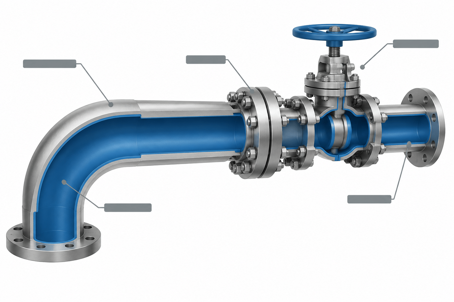
Lined piping CAD work requires more than assigning a material label to ordinary pipe geometry. The model and drawings must distinguish the structural pressure boundary from the internal barrier while communicating where that barrier continues, terminates, or changes construction.
The guidance below focuses on practical modeling, specification, and detailing decisions. It is intended to help designers identify information that must be verified through the project piping specification, approved supplier data, and fabrication documentation rather than inferred from a generic CAD component.
Lined piping combines a structural pressure-containing component with an internal barrier selected for corrosion resistance, purity, abrasion resistance, or another service requirement. That construction creates a documentation challenge: a simple pipe centerline and nominal size do not communicate the complete assembly.
For CAD users, the important questions include where the lining begins and ends, whether it continues through fittings, how joints preserve the barrier, and which dimensions are controlled by a manufacturer. A model can look connected while omitting a liner discontinuity, restricted bore, special flange detail, or fabrication limitation.
This guide explains how to represent lined piping without assuming that every lined system uses the same materials, dimensions, or joint design. Actual component geometry and fabrication requirements must come from the applicable piping specification, approved vendor information, and project documentation.
What Is Lined Piping?
A lined piping component has an internal layer that performs a function different from the outer pressure boundary. The outer pipe, fitting, or vessel connection generally supplies structural strength and pressure containment. The internal barrier separates the conveyed fluid from some or all of that outer material.
The broad term may include several constructions:
- Bonded or adhered internal linings
- Loose or mechanically retained liners
- Factory-molded lined fittings
- Internally coated pipe where the coating is treated as a functional barrier
- Composite constructions supplied as proprietary component systems
These constructions are not automatically interchangeable. Their end details, allowable fabrication methods, temperature limitations, inspection requirements, and dimensional effects can differ. A CAD library should therefore avoid treating “lined” as only a graphical color or generic note.
Lining Is Not the Same as Corrosion Allowance
Corrosion allowance is additional material included in the pressure-containing wall to account for anticipated metal loss. A lining is a distinct internal barrier. Although both concepts relate to service life and material compatibility, they affect documentation differently.
Corrosion allowance is normally carried as engineering data and does not appear as a separate layer in ordinary piping geometry. A lining may affect the available bore, component ends, sealing surfaces, fabrication sequence, inspection, and replacement method. It may also require special fittings or factory-fabricated spools.

Do not subtract a stated corrosion allowance from the modeled wall and then call the result a lined bore. Likewise, do not assume that a lined component has no corrosion allowance. Both requirements must be read from the governing specification.
What Geometry Should the CAD Model Show?
Outside envelope
For general arrangement and clash detection, the external envelope is usually the first priority. It must represent the actual lined pipe, fitting, flange, valve, or proprietary component closely enough for routing and access review.
The outside diameter of a lined straight pipe may resemble that of its metallic carrier pipe, but complete component envelopes are not necessarily standard across suppliers. Lined fittings can have different body shapes, flange arrangements, or face-to-face dimensions from unlined fittings that share the same nominal size.
Never replace an unknown lined fitting with a standard unlined fitting merely because the ports connect in the model. Use approved manufacturer dimensions or mark the item as preliminary until verified.
Internal bore
The lining occupies space inside the component, so the clear bore can be smaller than the bore inferred from the carrier pipe schedule alone. The effect may be important at reducers, valves, instrument connections, equipment nozzles, and locations requiring cleaning or internal access.
A full internal liner solid is not always necessary in a plant model. However, the bore information should remain available as component data or controlled documentation when it affects hydraulic review, piggability, cleaning, inspection, or nozzle compatibility.
End and face details
The most important geometry is often at the ends. Depending on the selected system, lining material may terminate before an end, extend over a sealing face, be retained by a special feature, or connect to another lined component through a proprietary joint arrangement.
Modeling only the outer flange faces can hide the actual liner interface. Connection records should identify the end type and whether the barrier remains continuous across the joint.
Key Differences Between Lined and Unlined Components
| Design issue | Unlined component assumption | Lined piping check |
|---|---|---|
| Clear bore | Often derived from pipe size and wall data | Verify the finished internal opening after lining |
| Fitting dimensions | May follow a familiar dimensional family | Use the selected lined fitting or vendor dimensions |
| Joint sealing | Defined by the standard end connection and gasket arrangement | Confirm how the lining terminates and participates in sealing |
| Field cutting | May be permitted under the project fabrication procedure | Do not assume the liner can be cut, repaired, or re-formed in the field |
| Welding | Controlled by base material and joint procedure | Check liner removal, protection, restoration, and heat limitations |
| Inspection | Focuses on the pressure boundary and welds | May also require continuity, surface, holiday, adhesion, or other liner checks |
Joint Continuity Must Be Explicit
A lined route is only as effective as its interfaces. Every flange, valve, branch, instrument connection, equipment nozzle, and temporary closure can interrupt the internal barrier.
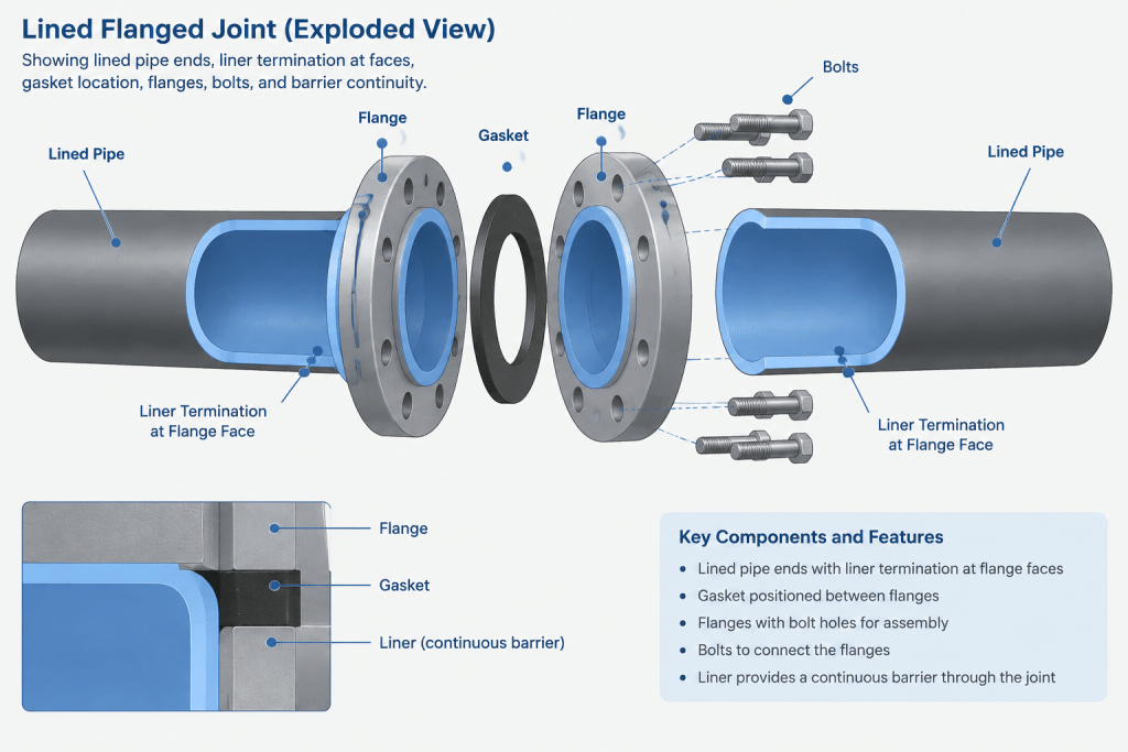
During model review, trace the line connection by connection and ask:
- Is each wetted component compatible with the specified lined service?
- Does the liner reach the joint in the required manner?
- Is the gasket or sealing arrangement compatible with the facing and lining construction?
- Does a valve expose body or trim material that the line specification intends to isolate?
- Does an instrument branch introduce an unlined pocket?
- Is the connected equipment nozzle lined, clad, coated, or otherwise protected?
- Can the joint be assembled without damaging the lining?
A line designation applied to the pipe alone is insufficient. The continuity check must include every wetted component.
Spool Planning and Fabrication Constraints
Lined piping often requires more deliberate spool planning than ordinary fabricated pipe. Shop processes may need access to component ends, controlled preparation, curing, inspection, or special handling. Field modification may be limited or prohibited by the selected lining system.
Before fixing spool breaks, coordinate:
- Maximum and minimum fabricable spool arrangements
- Access needed to apply and inspect the lining
- Whether branches can be lined after fabrication
- Permitted field joints and closure methods
- Transportation and handling protection
- Orientation requirements for non-symmetrical components
- Repair procedures for damaged areas
A convenient CAD spool break is not necessarily a practical lining break. Fabricator review should occur before drawings are released for construction.
Branches, Drains, and Instrument Connections
Small connections deserve special attention because they can create exposed edges, narrow passages, trapped material, or inaccessible areas. A generic branch symbol does not establish that a particular lining process can be applied continuously through the opening.
Identify the actual branch construction rather than assigning a generic reducing connection. Record the branch size, end type, orientation, and liner requirement. Where a connection is supplied as part of a proprietary lined fitting, model and list it as that component instead of constructing it from unrelated standard parts.
Low-point drains and dead-end branches should also be reviewed for cleanability and liner inspection. These are process and materials questions as well as drafting questions.

How to Carry Lining Data in CAD
A reliable model separates geometric data from specification data while keeping them linked. Useful component or line attributes may include:
- Lining or coating type designation
- Applicable piping material class
- Manufacturer and catalog identity when approved
- Finished bore or bore-status field when relevant
- End-detail designation
- Shop-lined or field-applied status
- Inspection or testing note reference
- Repair restriction or special handling flag
Avoid placing every attribute visibly on the drawing. Use concise callouts and schedules, while retaining detailed data in the model, line list, component records, or specification. The visible note should direct users to controlled requirements rather than attempting to reproduce an entire lining procedure.
Drawing and Isometric Checklist
Before issuing a lined piping drawing or isometric, verify the following:
- The line is identified as lined wherever it appears across drawings and model areas.
- Component dimensions come from the correct lined product data rather than unlined placeholders.
- Flanged and proprietary joint faces are oriented and located correctly.
- Reducers, branches, valves, and instrument connections preserve the intended barrier.
- Spool breaks reflect the lining supplier’s fabrication constraints.
- Field welds, field cuts, and adjustment pieces are not assumed to be permissible.
- Equipment nozzle interfaces have a defined material and lining transition.
- Finished bore restrictions are communicated where they affect operation or inspection.
- The bill of materials distinguishes lined components from visually similar unlined items.
- Special protection, handling, and inspection notes reference controlled project documents.
Common CAD Errors
One frequent error is using an unlined fitting model and adding “lined” to its description without checking dimensions. Another is showing lining on straight pipe while ignoring valves, gaskets, branches, and equipment interfaces. Designers may also assume that a field-fit spool can be trimmed like ordinary pipe, even though cutting could expose or damage the barrier.
Over-modeling can create problems as well. A detailed liner solid is not useful if it is based on guessed thickness or termination geometry. When verified internal geometry is unavailable, use a controlled simplified representation and clearly identify the unresolved data.
A Practical Modeling Principle
Treat lined piping as an assembly system, not as standard pipe with an added visual layer. Model the verified external envelope, preserve the information needed to understand the finished bore, and explicitly control every interface where the lining terminates or continues.
The final authority should be the project piping specification, approved component data, fabrication procedure, and supplier documentation. CAD geometry supports coordination, but it does not establish material compatibility or prove that a lined assembly is suitable for service.
Managing Lined Piping Through the Design Workflow
A useful workflow begins by separating confirmed information from provisional information. The line class may establish that a barrier is required, but it does not necessarily define the finished bore, external envelope, end treatment, or fabrication limits of every component. Those details should remain flagged until supported by approved product data.
During preliminary routing
Use a controlled placeholder only when verified component geometry is unavailable. The placeholder should identify the item as preliminary and should not silently inherit dimensions or connection behavior from a visually similar unlined part. Reserve adequate coordination space for the eventual component envelope, joint access, handling, and maintenance needs.
During component selection
Confirm that each pipe section, fitting, valve, branch, gasketed interface, instrument connection, and equipment transition belongs to the intended lined system. Matching nominal connections in CAD does not prove barrier continuity, sealing compatibility, or fabrication compatibility.
During model review
Review the route as a sequence of wetted interfaces rather than as an uninterrupted centerline. At each connection, establish what material the process fluid encounters and whether the barrier is continuous, deliberately terminated, or transitioned to another protected surface.
During drawing issue
Ensure that the isometric, bill of materials, line data, and component records communicate the same lined-service requirement. A note on the drawing cannot correct an incorrectly selected catalog item, and a correct model attribute may be missed if the issued deliverables do not expose it where fabrication and inspection personnel need it.
Responsibility and Data Handoffs
Lined piping commonly involves several technical disciplines and an external supplier or fabricator. Clear handoffs reduce the risk that an unresolved liner detail will be treated as a drafting assumption.
- Process and materials engineering: define the required service barrier, compatibility basis, and relevant operating or cleaning considerations.
- Piping design: route the system, select the appropriate component family, control interfaces, and provide space for assembly and access.
- Supplier or fabricator: confirm manufacturable geometry, end construction, spool limitations, repair methods, and inspection provisions.
- Equipment and instrumentation teams: define protected nozzle, valve, and branch interfaces that form part of the wetted boundary.
- Document control and CAD administration: keep approved component records, model attributes, schedules, and revisions aligned.
Any unresolved interface should be recorded as an open technical item rather than concealed by a complete-looking model. Final geometry and service suitability require review against controlled project and supplier documentation.
Frequently Asked Questions About Lined Piping CAD
Should the lining always be modeled as a separate solid?
No. A separate liner solid may be useful for interface studies, bore review, or detailed fabrication coordination, but it is not automatically required for every plant model. The chosen representation should preserve verified external geometry and make relevant internal restrictions and end details available without introducing guessed geometry.
Can an unlined fitting model be reused for a lined fitting?
Only when approved information confirms that the required geometry and interfaces are equivalent for the intended modeling purpose. Adding a lined-service description to an unlined catalog item does not verify its envelope, face arrangement, finished bore, or fabrication requirements.
How should unknown liner details be shown?
Use a controlled simplified representation and identify the unresolved information in the component status, model notes, or design action register. Do not invent liner thickness, termination geometry, or finished bore merely to make the model appear complete.
Why is barrier continuity important at flanges and valves?
These interfaces may expose materials that the lining is intended to isolate. The end treatment, sealing arrangement, valve construction, and adjacent component must work together to maintain the required wetted boundary.
Can lined pipe be field cut or adjusted?
That cannot be assumed. Cutting may expose, loosen, deform, or otherwise damage the internal barrier. Any field modification must follow the approved fabrication and repair requirements for the selected lining system.
What should appear in the bill of materials?
The bill of materials should identify the approved lined component rather than describe it as an ordinary component with an informal note. The exact fields and designations should follow the project specification, catalog structure, and procurement workflow.
Does a connected CAD model prove the assembly is suitable?
No. CAD connectivity demonstrates geometric relationships within the model. It does not establish chemical compatibility, pressure integrity, sealing performance, manufacturability, inspectability, or fitness for service.