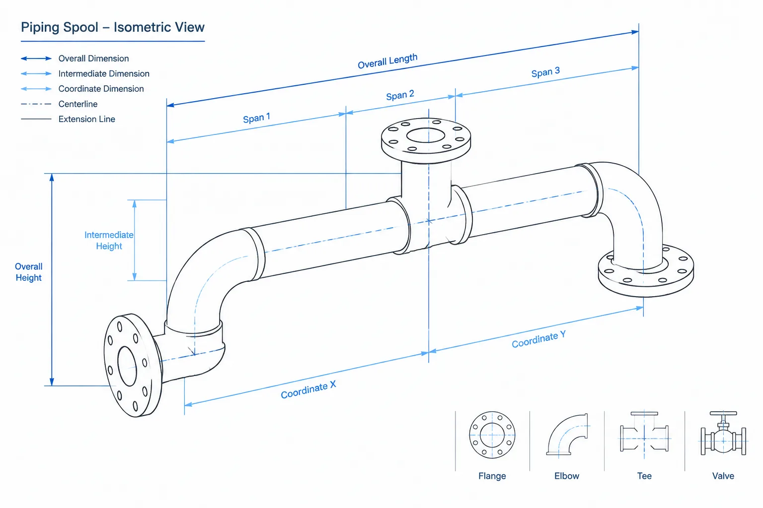
Piping isometric dimensioning should define the spool through a clear hierarchy of fixed interfaces, fabrication geometry, item locations, and derived information. The objective is not to maximize the number of dimensions. It is to communicate the geometry that fabrication and installation must follow while avoiding redundant values that can become inconsistent.
The guidance below explains how to distinguish controlling dimensions from calculated or reference values, select dependable dimension endpoints, account for component geometry, and review field interfaces. Project specifications, approved component data, and established drafting conventions remain the governing basis for any issued isometric.
A piping isometric must communicate enough information to fabricate, assemble, and locate a pipe spool without turning the drawing into a crowded collection of measurements. Effective piping isometric dimensioning is therefore not a matter of labeling every visible length. It is a matter of identifying which points control the installation, which dimensions control fabrication, and which values can be derived reliably from component data and connected geometry.
The central question is simple: if a dimension were removed, could the intended spool still be fabricated and installed unambiguously? If the answer is no, the dimension is probably necessary. If the same value can be calculated from several other stated dimensions, adding it may create a conflicting dimension loop rather than useful information.
What a piping isometric dimension controls
Dimensions on an isometric generally serve one of three purposes: locating the piping in the plant, defining the fabricated assembly, or locating an item along the pipe. These purposes are related, but they should not be treated as interchangeable.
Plant-location dimensions
Plant-location dimensions connect the spool to the project coordinate system or to established equipment and structural references. They may locate:
- Equipment nozzle centerlines
- Pipe centerlines at tie-ins
- Wall, floor, or platform penetrations
- Branch centerlines
- Changes in elevation
- Connections to existing piping
These are often the dimensions that determine whether the spool fits its surroundings. A perfectly fabricated spool can still be unusable if its terminal points are referenced to the wrong datum or if a tie-in coordinate is incorrect.
Fabrication dimensions
Fabrication dimensions define the geometry needed to cut pipe and assemble components. Typical examples include straight centerline runs between fitting intersections, branch locations, and the relative positions of weld-end components.
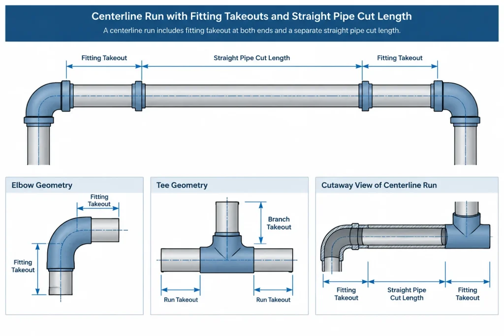
A centerline dimension is not automatically a pipe cut length. Elbows, tees, reducers, flanges, valves, and other components consume part of the dimensioned run. Their takeout, center-to-end, end-to-end, or face-to-face values must be applied using the governing project component data. The resulting cut length belongs in the fabrication workflow or cut list rather than being inferred casually from the plotted line.
Item-location dimensions
Some components require a defined position even though they do not change the main routing. Examples include supports, instrument connections, vents, drains, small branches, and special attachments. Their locations should be referenced to a stable point that will remain identifiable during fabrication and installation.
Referencing an attachment from an uncertain field end, an unverified existing feature, or another loosely located item can transfer uncertainty through the spool.
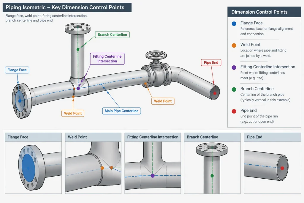
Dimension to functional control points
An isometric is easier to check when dimensions terminate at recognizable control points. Depending on the connection and project convention, these may include:
- Equipment nozzle faces or centerlines
- Flange faces
- Fitting centerline intersections
- Branch centerlines
- Weld locations
- Pipe ends prepared for field connection
- Tie-in points
- Established grid lines, column lines, or project coordinates
The selected point must be clear. A dimension ending near a flange could be interpreted as running to the face, flange centerline, weld, or pipe end. Graphic proximity is not enough; extension lines, symbols, and notes should identify the intended endpoint.
Dimensions should also follow one consistent geometric basis. A chain that begins with centerline intersections but ends at flange faces may be valid, yet the transition must be deliberate and checkable. Mixing endpoints without recognizing component takeout is a common source of cut-length errors.
Overall, intermediate, and coordinate dimensions
Different dimension types answer different questions. A balanced isometric uses them selectively.
| Dimension type | Primary purpose | Common risk |
|---|---|---|
| Overall dimension | Confirms the total distance between major terminal or control points | May not locate intermediate fittings or branches |
| Intermediate dimension | Locates a change in direction, branch, component, or attachment | Long chains can accumulate uncertainty |
| Coordinate or elevation | Relates a point directly to the project datum | Can conflict with chained dimensions if revisions are incomplete |
| Reference dimension | Provides convenient derived information | May be mistaken for a controlling requirement |
Overall dimensions are valuable checks, but they rarely define an entire spool by themselves. Intermediate dimensions establish the internal geometry. Coordinates and elevations are especially useful at interfaces where location matters more than the length of any single pipe segment.
When both chained and overall dimensions are shown, the drawing team should identify which set controls. Otherwise, a small revision to one segment can leave the overall value inconsistent with the dimension chain.
Dimensions that are usually derived
Not every fabrication value needs to appear as a controlling drawing dimension. Some information is commonly derived from verified component geometry and the dimensioned pipe centerline layout. Examples may include:
- Individual pipe cut lengths after fitting takeout is applied
- Diagonal lengths calculated from coordinate differences
- Component envelope dimensions available from approved project data
- Repeated values governed by a standard detail or project specification
- Secondary overall dimensions that duplicate a complete dimension chain
Leaving a value derived is appropriate only when the inputs are controlled. A model-generated length is not trustworthy merely because software calculated it. The component definition, connection point, end preparation, and routing geometry must all be correct.
If a derived value is shown for convenience, it should be distinguishable from the dimensions that establish fabrication or installation requirements. Project drafting practices may use parentheses, a note, or another convention for reference information. The project convention should be followed consistently rather than assumed.
How fittings affect dimension interpretation
The apparent length of a line on an isometric does not reveal where the pipe ends and the fitting begins. A run dimension between two fitting intersections includes the geometric influence of both fittings. To obtain the pipe cut length, the applicable fitting dimensions must be deducted or otherwise accounted for.
This distinction becomes especially important around reducers, trimmed fittings, nonstandard bends, valves, specialty items, and fabricated branches. A generic symbol may not represent the actual component envelope or connection locations. Before releasing the isometric, confirm that the model or drafting library uses the correct project-controlled dimensions.
Do not scale an isometric to recover missing information. Isometrics are commonly arranged for readability rather than plotted as measurable orthographic views. The stated dimensions and coordinates, not the visual line length, control the geometry.
Dimensioning sloped and offset piping
Sloped lines and multi-axis offsets require special care because a single apparent run may contain horizontal, vertical, and lateral components. The drawing should provide enough information to reconstruct the intended endpoints and orientation without measuring the graphic.
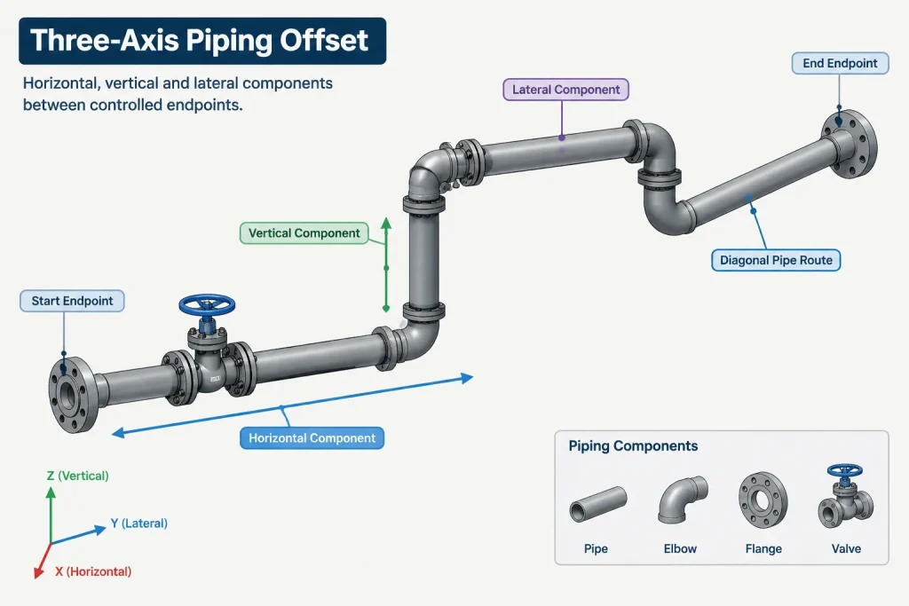
A useful approach is to define the endpoint coordinates or the component changes along the relevant plant axes. The true pipe length can then be calculated from the controlled geometry. For sloped piping, the required slope notation and at least one reliable elevation relationship should be carried consistently through the run.
A diagonal length alone may establish distance but not direction. Conversely, coordinate differences can establish direction and permit the true length to be derived. The preferred method depends on the project workflow, but it must support independent checking.
Field welds, tie-ins, and uncertain endpoints
Field interfaces deserve more explicit dimensioning than routine shop joints. Existing piping may not match historical drawings, and equipment nozzle positions may change during vendor coordination or installation.
At these interfaces, identify the point that is verified, the direction in which adjustment is permitted, and any dimension that remains subject to field confirmation. Do not present an assumed existing location as an exact surveyed condition. If a field-fit segment is planned, its documentation should make clear which adjacent geometry is fixed and where final trimming or adjustment occurs.
Tie-in dimensions should be traceable to field measurements, approved interface data, or project coordinates. The drawing should not rely on a chain beginning at an unrelated spool feature when a direct interface reference is available.
A practical isometric dimensioning workflow
- Mark the fixed interfaces. Identify nozzles, tie-ins, penetrations, and other points controlled outside the spool.
- Confirm the datum system. Check plant axes, coordinates, elevations, units, and drawing orientation.
- Trace the centerline path. Follow every change in direction and verify that the route is geometrically complete.
- Locate branches and inline items. Dimension each from a stable, identifiable control point.
- Check component endpoints. Distinguish faces, centers, weld ends, and theoretical fitting intersections.
- Review takeout data. Confirm that component geometry comes from the applicable project specification, catalog data, or approved model library.
- Remove unnecessary duplication. Eliminate dimensions that create conflicting closed loops unless they are clearly identified as reference checks.
- Recalculate independently. Verify totals, offsets, elevations, and cut-length logic without relying solely on the displayed CAD values.
- Review field interfaces separately. Confirm survey status, fit-up strategy, and any hold dimensions before issue.
Final review questions
Before an isometric is released, a reviewer should be able to answer the following:
- Are both terminal points unambiguously located?
- Can every change in direction be reconstructed from stated geometry?
- Are branch and attachment locations referenced from stable points?
- Is each dimension endpoint clearly a face, centerline, weld, pipe end, or intersection?
- Can cut lengths be determined using verified component takeout data?
- Are coordinate, elevation, and chained dimensions mutually consistent?
- Are derived or reference values distinguishable from controlling dimensions?
- Have tie-ins and existing conditions been verified rather than assumed?
- Would fabrication still be possible without scaling the drawing?
Good piping isometric dimensioning creates a traceable geometric definition rather than a dense drawing. By prioritizing fixed interfaces, stable references, clear endpoints, and verified component geometry, the isometric becomes easier to fabricate, check, revise, and install.
Managing dimension authority through revisions
A dimensioning scheme should remain understandable after the routing, component selection, or interface data changes. Reviewers need to know which information establishes the geometry and which information merely confirms or summarizes it. Without that hierarchy, a revision can update one value while leaving a duplicate overall, coordinate, or reference value unchanged.
Identify the source of each controlling value
Important dimensions should be traceable to their design basis. An interface location may originate from approved equipment information, a field survey, a project coordinate, or a structural reference. Internal spool geometry may originate from the routed centerline and approved component definitions. Recording that distinction in the project workflow helps prevent derived model output from being treated as independently verified input.
Review the effect of a change, not only the changed dimension
When a control point moves, the review should extend through every dependent feature. Branch positions, support locations, fitting takeout, spool limits, weld locations, and connected coordinates may all be affected even if their displayed annotations do not move automatically. A successful CAD update is not, by itself, proof that the revised isometric is complete.
Keep fabrication and installation handoffs consistent
The isometric, bill of materials, cut information, spool identification, and field documentation should describe the same connection points and component geometry. If one deliverable uses fitting intersections while another uses component faces or weld ends, the conversion must be intentional and based on approved data. Clear endpoint terminology reduces the chance that different teams will apply different interpretations to the same run.
Practical rule for deciding whether to show a dimension
Show a value as controlling when it is needed to establish location, orientation, assembly geometry, or an item position that cannot be recovered unambiguously from other controlled information. Leave it derived when approved inputs already define it completely and displaying it would add an unnecessary closed loop.
If a calculated value is useful for checking, label or format it according to the project convention for reference information. The drawing should make its authority clear rather than expecting the reader to infer status from placement alone.
Piping Isometric Dimensioning FAQ
Should every straight pipe segment have a displayed dimension?
No. Every segment must be determinable, but that does not mean every segment requires a separate controlling dimension. A value may remain derived when controlled coordinates, elevations, centerline geometry, and component data define it without ambiguity.
Why is a centerline run not necessarily the pipe cut length?
A centerline run can include portions occupied by fittings, flanges, valves, reducers, or other components. The pipe cut length depends on the actual connection points and the approved takeout, center-to-end, end-to-end, or face-to-face information for those components.
Can an overall dimension replace intermediate dimensions?
Usually not when the spool contains changes in direction, branches, or items that require defined positions. An overall dimension confirms terminal separation, while intermediate dimensions or coordinates establish the internal geometry.
How should a reference dimension be treated?
A reference dimension is convenient derived information rather than an independent geometric requirement. It should be distinguished according to the applicable project drafting convention so that fabrication personnel and reviewers do not mistake it for the controlling value.
What is the safest reference for a branch or attachment?
Use a stable and identifiable control point that remains available during fabrication or installation. Avoid building a location chain from an uncertain field end, an assumed existing condition, or another feature whose own position is not firmly controlled.
Can dimensions be obtained by scaling a piping isometric?
No. The isometric graphic is arranged to communicate routing and component relationships, not to serve as a measurable view. Stated dimensions, coordinates, elevations, notes, and approved component geometry govern.
What should be checked when a tie-in location is uncertain?
Confirm the verified reference, survey status, permitted adjustment direction, field-fit strategy, and geometry that must remain fixed. An assumed existing location should not be presented as confirmed field information.