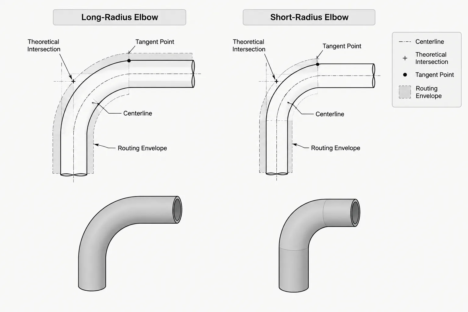
Comparing long-radius vs short-radius elbows requires more than checking which fitting occupies less space. Radius selection influences the routed centerline, fitting takeout, connected pipe lengths, weld positions, clearance envelopes, and the way a spool is documented for fabrication.
This guide explains how to evaluate those differences during piping layout and CAD modeling. It is intended to support design review, not replace the governing piping specification, approved dimensional source, process requirements, or manufacturer data.
Long-radius and short-radius elbows can turn a piping route through the same nominal angle, but they are not interchangeable pieces of geometry. Their different centerline radii affect fitting takeout, pressure loss, clearance, weld location, spool dimensions, and the space required to complete a change in direction.
For a piping designer, the important question is not simply which elbow fits inside the available space. The selected fitting must also agree with the piping specification, process requirements, applicable dimensional standard, material description, and fabrication method. CAD geometry should represent that verified selection rather than treating elbow radius as an adjustable graphic preference.
What Long Radius and Short Radius Mean
The terms long radius and short radius describe the relationship between an elbow’s centerline bend radius and its nominal pipe size. Common fitting standards define these relationships and provide corresponding center-to-end dimensions for particular elbow angles and sizes.
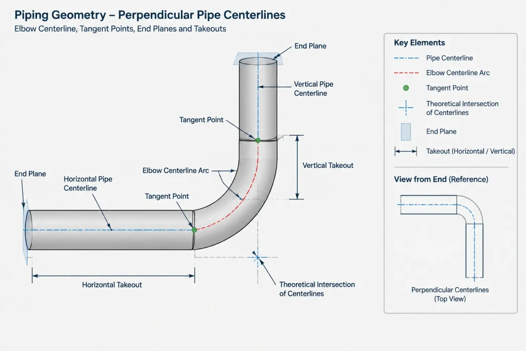
The bend radius is measured from the theoretical center of curvature to the pipe centerline. It is not the outside radius of the fitting, and it is not automatically the same as the fitting’s center-to-end dimension. Center-to-end dimensions depend on both the bend geometry and the included angle.
In general, a long-radius elbow makes a broader turn, while a short-radius elbow makes a tighter turn. Both terms must still be paired with other information, including:
- Nominal pipe size or DN designation
- Elbow angle
- End connection type
- Wall designation or matching bore requirement
- Material and fitting specification
- Seamless, welded, forged, cast, or fabricated construction where relevant
An annotation that says only “elbow” does not completely define a purchasable or fabricable component.
Practical Differences Between the Two Elbow Types
| Consideration | Long-radius elbow | Short-radius elbow |
|---|---|---|
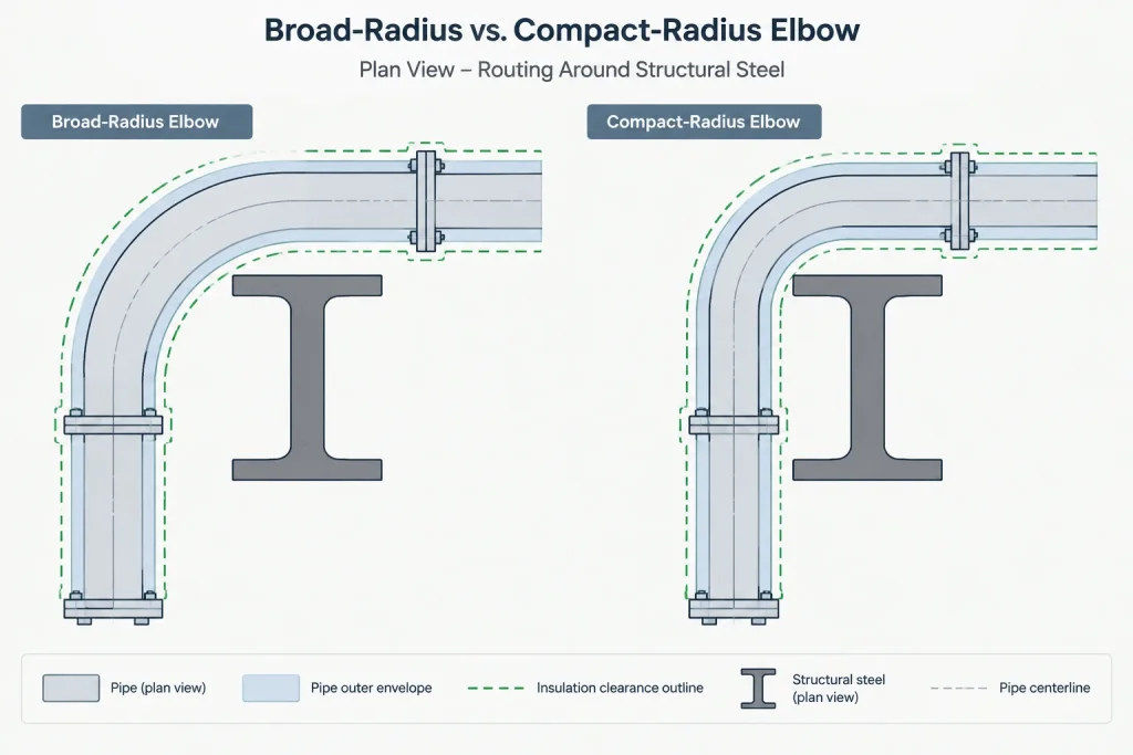
| Routing envelope | Requires more space around the change in direction | Fits within a more compact routing envelope |
| Flow path | Provides a more gradual change in direction | Produces a tighter change in direction |
| Fitting takeout | Generally extends farther from the theoretical intersection | Generally has a smaller takeout |
| Spool geometry | May reduce the straight length available between nearby components | Can recover space in congested layouts |
| Specification use | Commonly used where a broader turn is preferred | Used where permitted and where compactness is important |
| CAD substitution | Cannot be replaced by a short-radius elbow without changing connection points | Cannot be replaced by a long-radius elbow without changing the route |
This comparison is directional rather than a selection rule. The actual choice belongs to the governing project documents and engineering review.
Flow and Service Considerations
Changing fluid direction creates disturbance and pressure loss. A broader turn generally changes direction more gradually than a compact elbow, but elbow selection cannot be based on that observation alone. Flow velocity, fluid properties, solids content, erosion potential, noise, vibration, and the arrangement of nearby fittings may all matter.
Services carrying slurries or entrained solids may require particular attention to wear at the elbow. Systems subject to pulsation, high velocity, or severe cyclic conditions may also need review beyond ordinary layout practice. Hygienic, lined, jacketed, internally coated, or piggable piping can impose additional restrictions on internal geometry and fitting construction.
A CAD model should not be treated as evidence that a tight turn is acceptable for the service. When process or mechanical requirements control elbow selection, those requirements should be established in the line class, piping specification, specialty item documentation, or engineering notes.
Why Elbow Radius Changes the CAD Layout
Connection points move
For a fixed theoretical intersection, changing the elbow radius changes the tangent points and end locations. If a designer swaps elbow types while keeping adjacent straight pipe unchanged, the assembled route will no longer reach the same endpoints.
This is especially important near equipment nozzles, flange faces, valves, branch fittings, and fixed tie-in coordinates. A fitting substitution may appear minor in a parts list but can alter an entire spool.
Weld locations move
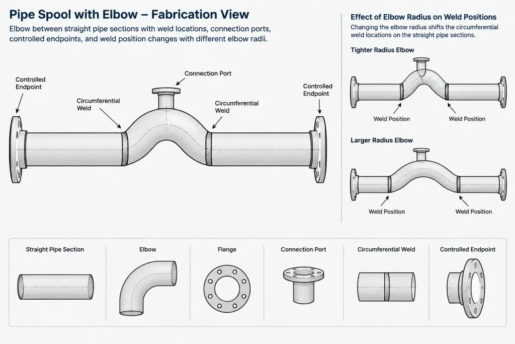
Butt-weld elbow ends define circumferential weld locations. A radius change moves those welds along both connected pipe legs. That movement can affect support proximity, examination access, field-weld planning, insulation terminations, and minimum straight-run requirements associated with other components.
The clearance envelope changes
The pipe centerline is only part of the required envelope. Designers must account for the fitting body, pipe outside diameter, insulation, heat tracing, cladding, nearby structural steel, and access needed for fabrication or inspection. A long-radius centerline that clears an obstruction may still produce an insulated fitting envelope that clashes with it.
Cut lengths change
Pipe cut length is derived after subtracting fitting takeouts and other component dimensions from controlled spool dimensions. Replacing one elbow type with another therefore changes the connected straight-pipe lengths. Scaling a fitting block or editing only its arc does not create reliable fabrication geometry.
Do Not Confuse Radius with Angle
Elbow angle and elbow radius describe different characteristics. A piping route may use elbows with different included angles, and those elbows may also be offered in different radius families. The angle controls how much the route changes direction; the radius controls how broadly that change occurs.
This distinction matters when reading fitting descriptions and building CAD libraries. A component name should identify both characteristics rather than relying on a generic symbol. The model ports, centerline arc, end planes, and metadata must all correspond to the same fitting definition.
A Reliable CAD Placement Workflow
- Confirm the piping specification. Determine which elbow type, connection, material, and wall designation are permitted for the line.
- Verify the dimensional source. Use the applicable project-approved fitting table or manufacturer data. Do not derive production dimensions from a schematic symbol.
- Establish the route intersection. Locate the theoretical intersection of the incoming and outgoing pipe centerlines.
- Apply the correct takeout. Place tangent or connection points using the verified center-to-end geometry for the fitting size and angle.
- Check adjacent straight lengths. Confirm that valves, branches, instruments, welds, and supports are not crowded by the revised elbow ends.
- Model the full envelope where needed. Include insulation or other outer layers for clash-sensitive areas.
- Update component data. Make sure the elbow description, catalog identifier, radius designation, end type, and bill-of-material entry agree with the geometry.
- Review the resulting spool. Recheck dimensions, weld locations, transport limits, field fit-up strategy, and access.
Common Drafting and Modeling Errors
- Using one elbow block for every radius: Changing a label without changing ports and takeout creates a geometry-data conflict.
- Scaling an elbow symbol: Uniform scaling can alter pipe diameter as well as radius, while nonuniform scaling distorts the fitting.
- Holding both endpoints after a substitution: A different-radius elbow cannot normally occupy the same centerline intersection and retain the same connected straight lengths.
- Checking only the centerline: The fitting body and insulation may clash even when the route line appears clear.
- Assuming short radius is always available: Availability and permission depend on the fitting type, size range, material system, specification, and supplier.
- Using catalog geometry as a process decision: The presence of a component in a CAD catalog does not mean it is acceptable for a particular service.
When a Tight Layout Needs Another Solution
If a long-radius elbow does not fit, changing automatically to a short-radius elbow is only one possible response. The designer may instead move the route, change elevation, revise equipment spacing, use a different fitting arrangement, or coordinate a fabricated bend where the specification permits it. Each option changes geometry, cost, fabrication, and potentially system behavior.
The correct approach is to identify what is fixed and what can move. Equipment nozzle locations, building penetrations, tie-ins, and required access zones may be hard constraints. Pipe rack lanes, support locations, and intermediate spool geometry may offer more flexibility. Recording these constraints helps reviewers understand why a particular routing solution was chosen.
Final Review Checklist
- Is the radius designation permitted by the piping specification?
- Does the modeled angle match the component description?
- Are center-to-end dimensions taken from a verified source?
- Do ports, tangent points, and end planes match the visible geometry?
- Have connected pipe cut lengths been recalculated?
- Are welds clear of nearby fittings, supports, and inaccessible zones?
- Has the insulated or lined envelope been checked where applicable?
- Does the bill of material identify the actual elbow type?
- Have process, mechanical, and fabrication concerns been reviewed when the fitting type changes?
Long-radius and short-radius elbows are best treated as distinct components, not alternate graphics for the same turn. Keeping the selected radius, verified dimensions, CAD ports, and component data synchronized prevents a compact layout decision from becoming a spool-fit or procurement problem later in the project.
Using the Comparison in a Design Review
A useful elbow review begins by separating fixed project points from geometry that can be adjusted. Equipment nozzles, tie-ins, penetrations, and flange faces may be controlled locations. Tangent points, intermediate pipe lengths, support positions, and some weld locations may depend on the selected elbow geometry.
When the radius family changes, reviewers should follow the effect through the entire connected route rather than examining the fitting in isolation. The revised model should still agree with spool dimensions, component descriptions, material data, clearance requirements, and the bill of material.
Document the Reason for a Radius Change
A radius substitution should have a traceable basis, such as an approved specification requirement, a verified routing constraint, or an engineering decision. Recording that basis helps fabrication, procurement, stress, process, and field personnel distinguish an intentional revision from an accidental catalog or modeling change.
Keep Geometry and Data Synchronized
The visible elbow, connection ports, centerline path, end planes, component metadata, and reported material item should describe the same fitting. If only the graphic or label changes, downstream drawings and reports may conflict with the model. This consistency is especially important when a model feeds isometrics, spool drawings, clash reviews, or material reports.
Frequently Asked Questions
Can a short-radius elbow replace a long-radius elbow without redimensioning the route?
Not normally. Changing the radius changes the elbow takeout, tangent locations, connection points, weld locations, and adjacent straight-pipe lengths. The connected route and spool dimensions must be reviewed again.
Does a long-radius elbow always produce less pressure loss?
A broader turn generally creates a more gradual directional change, but fitting selection should not rely on that observation alone. Fluid properties, velocity, solids, nearby fittings, service conditions, and project requirements can affect the engineering decision.
Is a centerline clash check sufficient for elbow clearance?
No. The review may also need to include the fitting body, pipe outside envelope, insulation, cladding, heat tracing, weld access, inspection access, and nearby structural or mechanical items.
What should change in CAD when the elbow radius changes?
The fitting geometry, ports, tangent points, end planes, connected pipe lengths, weld positions, component description, catalog assignment, and material reporting should all be checked for consistency.
Can an available CAD catalog component be assumed acceptable for the line?
No. Catalog availability confirms only that a model component exists. Acceptance must come from the applicable piping specification, approved dimensional information, service requirements, material definition, and project review process.
How should an elbow be identified in project documentation?
The description should distinguish the radius family and angle while also agreeing with the required size designation, end connection, wall or bore requirement, material specification, and construction method where applicable.