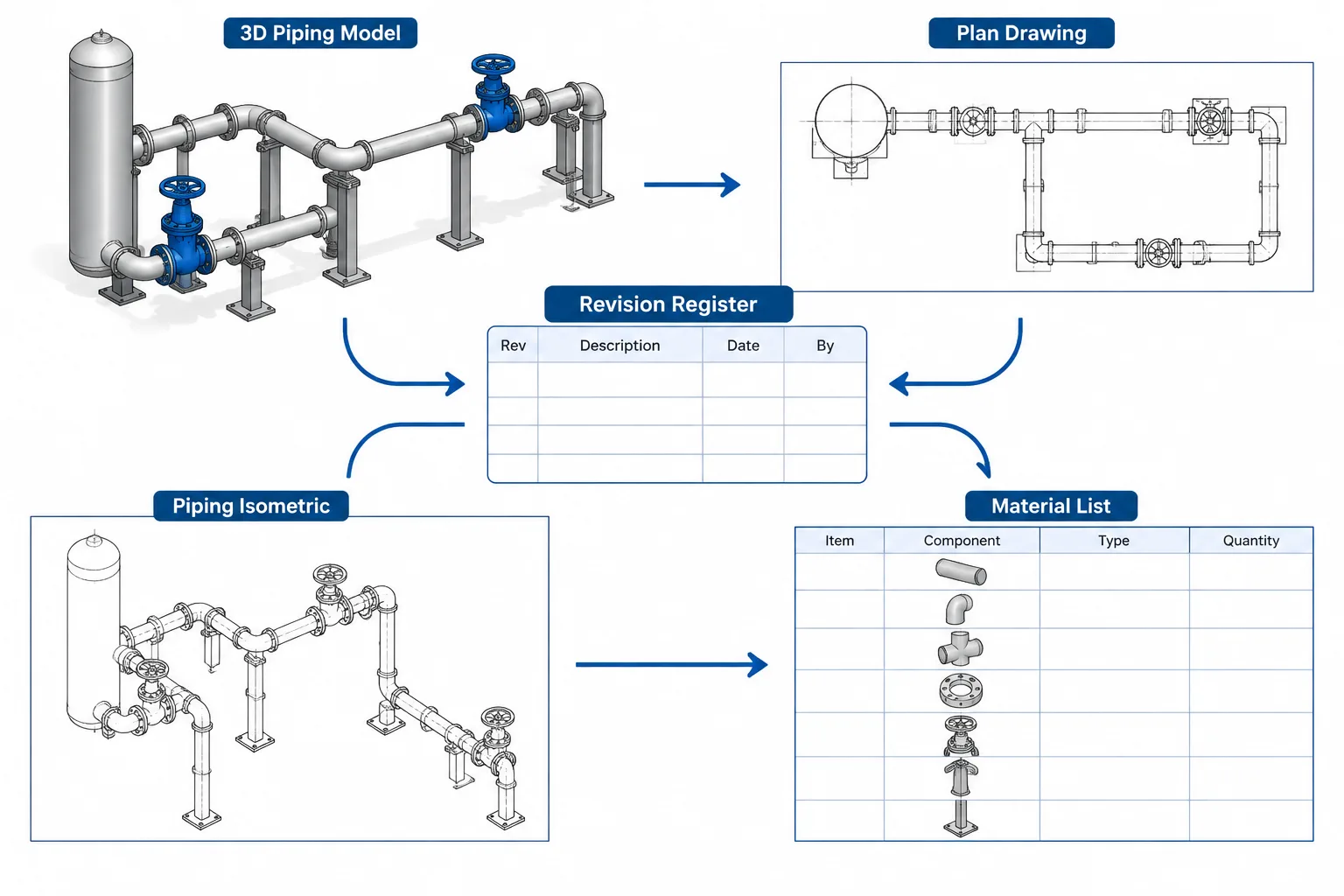
Piping CAD revision control is the coordinated management of changes across model geometry, object data, drawings, reports, and formal project issues. It helps the project team distinguish active design work from information that has been checked, authorized, and released for a defined purpose.
The guidance below explains how to establish the correct baseline, trace change impacts, document revisions, and verify connected deliverables. The exact identifiers, approval steps, status names, and clouding conventions should always follow the applicable project procedure.
Piping CAD revision control is more than adding a cloud to a drawing. A piping change can affect routed geometry, component data, equipment interfaces, isometrics, material quantities, support locations, and multiple drawings derived from the same model. If those effects are not tracked together, the project can issue documents that disagree even though each file appears complete on its own.
A reliable workflow distinguishes between a change in progress, a formally issued revision, and the current approved project baseline. It also records why the change occurred and which deliverables were affected. The goal is not to preserve every drafting action. The goal is to make consequential design changes traceable and prevent outdated information from being used for procurement, fabrication, construction, or operation.
What Revision Control Must Accomplish
Revision control should allow a project team to answer five practical questions:
- What changed?
- Why was it changed?
- Which model objects, drawings, lists, or calculations were affected?
- Who checked and authorized the issued result?
- Which issue represents the current baseline?
A revision identifier by itself cannot answer all five. It must work with issue dates, descriptions, approval records, document status, and the project’s document-control procedure.
Working Changes Are Not the Same as Issued Revisions
Designers routinely test routes, move fittings, replace valves, and adjust dimensions. These working edits may be saved many times before a drawing is ready for formal issue. Treating every save as an issued revision would create noise and make the history difficult to use.
An issued revision is a controlled project event. It establishes a new document state for a defined purpose, such as review, coordination, procurement, fabrication, construction, or record documentation. The exact status names and revision sequence should come from the project procedure rather than individual drafting preference.
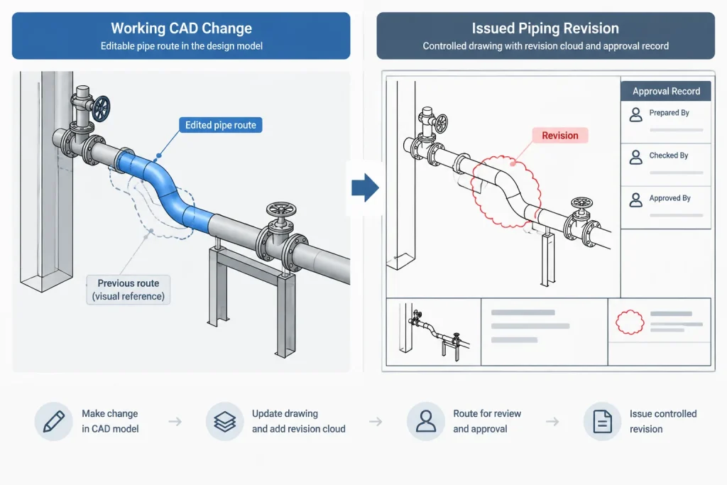
File history, model version history, and formal revision history therefore serve different purposes:
| Record | Primary purpose | Typical contents |
|---|---|---|
| Working file history | Recover or compare design development | Saves, backups, user edits, and interim options |
| Coordination record | Track comments and design decisions | Markups, review responses, clash actions, and meeting decisions |
| Issued revision record | Identify a formally released document state | Revision identifier, status, date, description, and authorization |
| As-built or record update | Document verified installed conditions | Accepted field changes and confirmed final configuration |
Control the Baseline Before Editing
Before revising piping information, identify the baseline being changed. Confirm the current controlled model, drawing issue, referenced vendor information, line list, equipment arrangement, and applicable piping specification. An old local file can look correct while omitting changes already incorporated elsewhere.
The designer should also determine whether related work is occurring in parallel. Two users may otherwise revise the same line for different reasons, with one update overwriting or invalidating the other. File reservation, model worksharing, change registers, or defined area ownership can reduce this risk, but the method must match the project’s CAD environment.
Trace the Change Through Connected Deliverables
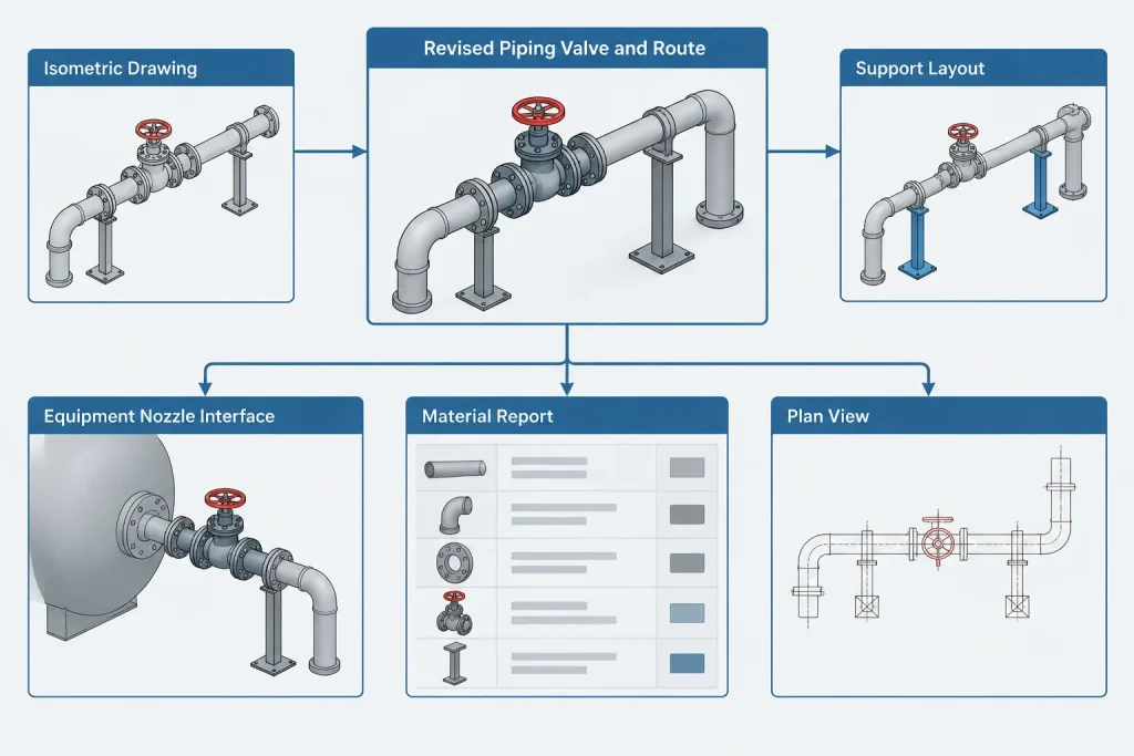
A piping revision rarely stops at the object that was edited. Moving a valve, for example, may alter adjacent pipe cut lengths, support relationships, operator access, insulation clearance, isometric dimensions, spool boundaries, weld locations, and material reporting.
Geometry
Check centerlines, elevations, fitting orientations, flange faces, branch locations, equipment nozzle interfaces, support positions, and required access envelopes. A visually small move may change fabrication dimensions or create a clash on another drawing.
Component and Line Data
Confirm that line numbers, nominal sizes, material classes, schedules or wall definitions, end connections, valve tags, and component descriptions still match the revised design intent. Copying geometry without updating its attached data can produce a correct-looking model and an incorrect bill of material.
Derived Documents
Regenerate or update affected isometrics, plans, sections, details, schedules, and material outputs using the project’s normal workflow. Do not assume that every deliverable updates automatically. Some drawings may contain manually placed dimensions, notes, symbols, or annotations that require separate review.
External Interfaces
Review equipment nozzles, structural openings, pipe supports, electrical interfaces, instrumentation connections, and vendor package boundaries. If the revision changes an interface owned by another discipline or supplier, coordinate it rather than silently adjusting only the piping model.
Revision Clouds and Markers
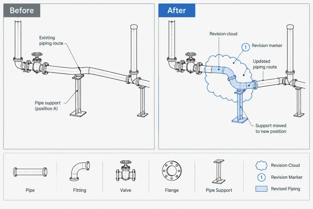
Revision clouds help reviewers locate visible drawing changes. A revision marker or delta can associate a cloud with an entry in the revision block. These graphics are navigation aids, not substitutes for a controlled description of the change.
Cloud the changed presentation at an appropriate scale. A cloud around an entire drawing can hide the actual scope, while a cloud around every minor line segment can make the sheet unreadable. Related edits may be grouped when that grouping makes the change easier to understand.
Not every model change produces a visible drawing change. Metadata corrections, hidden geometry changes, or updates outside a view’s crop may still affect schedules and downstream outputs. Conversely, a drawing annotation may change without altering the model. Revision review must therefore compare both graphical and non-graphical information.
Projects also differ on whether previous clouds remain, are removed, or are otherwise managed at the next issue. Follow the established document-control convention consistently; do not infer current scope solely from the clouds visible on an older sheet.
Write Useful Revision Descriptions
A good revision description is concise but specific enough to distinguish the change from routine drafting activity. Phrases such as “updated drawing” or “revised piping” provide little value. A better description identifies the affected system, area, interface, or design action without attempting to list every edited object.
Examples of useful description patterns include:
- Rerouted process line at equipment access area.
- Updated valve arrangement to match coordinated operating access.
- Revised branch connection and associated support layout.
- Updated equipment nozzle interface from accepted vendor information.
- Incorporated verified field routing into record drawing.
The wording should reflect what was actually authorized. Avoid implying that field conditions were verified if the update came only from a markup or unconfirmed report.
Separate Design Changes from Drafting Corrections
A design change alters technical intent, configuration, materials, interfaces, or functional requirements. A drafting correction improves the document without intentionally changing the design. Examples may include correcting a misspelled note, repairing a broken leader, or improving linework clarity.
The distinction matters because a design change may require multidisciplinary review or renewed technical checks. However, the designer should not decide informally that a correction is insignificant when it changes a dimension, tag, material description, or fabrication instruction. The project procedure should determine how corrections are classified and issued.
A Practical Revision Workflow
- Confirm the baseline. Open the current controlled files and identify the applicable issue status.
- Record the change source. Link the work to an approved markup, review comment, vendor update, field query, design decision, or other controlled input.
- Define the affected scope. Identify lines, equipment interfaces, drawings, isometrics, supports, and reports that may be involved.
- Edit geometry and data together. Update component properties and annotations rather than treating the model as graphics only.
- Run coordination checks. Review clashes, access, drainage or slope intent where applicable, support relationships, and discipline interfaces.
- Update derived outputs. Regenerate drawings and reports, then inspect manually maintained notes and dimensions.
- Compare against the baseline. Use visual and data comparisons where available, but verify the results rather than accepting every detected difference as meaningful.
- Apply issue documentation. Add the correct revision entry, status, descriptions, clouds, and markers according to project procedure.
- Complete checking and approval. Confirm that technical review covers the entire change impact, not only the clouded sheet area.
- Archive and release. Preserve the superseded controlled record and distribute the new issue through the authorized document system.
Common Revision-Control Failures
- Revising a superseded file: valid work is applied to an obsolete baseline.
- Updating the plan but not the isometric: construction documents show different routing or dimensions.
- Changing geometry without properties: tags and material reports retain old component data.
- Using clouds as the only record: the reason and authorization for the change cannot be recovered.
- Missing secondary effects: a route move leaves supports, openings, or access envelopes in their previous locations.
- Calling unverified information as-built: record documents imply field confirmation that did not occur.
- Replacing files without archiving: the team cannot reconstruct which information was previously issued.
Final Review Questions
Before releasing a revised piping deliverable, ask whether the correct baseline was used, the change source is traceable, and every affected output has been identified. Confirm that geometry, component data, annotations, material reports, and external interfaces agree. Check that the revision description communicates meaningful scope and that any clouding follows the project convention.
Effective piping CAD revision control creates a dependable chain from design input to issued result. When models, drawings, and data are reviewed as one connected system, revisions become easier to understand and less likely to create conflicting instructions downstream.
Build a Change-Impact Record
A practical change-impact record can connect the originating request with the model objects, drawings, isometrics, reports, interfaces, and review actions affected by the revision. This record does not need to duplicate the drawing revision block. Its purpose is to help the team identify dependencies that may not be visible on the issued sheet.
Useful entries describe the controlled input, affected system or area, responsible discipline, deliverables requiring review, and the disposition of each item. The record should distinguish confirmed impacts from items that still require investigation.
Compare Content, Not Just File Names
A changed file name or timestamp does not explain whether technical content changed. Comparison should consider routed geometry, component properties, tags, annotations, interfaces, and generated outputs. Automated comparison tools can help locate differences, but their results still require technical interpretation because some detected changes may be incidental while less visible data changes may be consequential.
Coordinate Model and Document Release
Where drawings and reports are derived from a shared model, release planning should identify which model state generated each deliverable. A drawing should not be treated as coordinated merely because it was regenerated. Manually maintained notes, dimensions, symbols, view settings, and external references may still require review.
The release package should also prevent superseded information from remaining in active circulation. Archiving preserves history, while controlled distribution makes the newly authorized baseline available to the people who use it.
Use Revision Control as a Verification Process
Revision control is most effective when it supports technical checking rather than functioning only as document administration. The checker should review the stated reason for the change, its direct edits, its secondary effects, and the agreement between model data and published deliverables.
No revision workflow can confirm that a change is suitable for a particular project without review against the governing design basis, project specifications, discipline requirements, vendor information, and verified field conditions.
Frequently Asked Questions
Is every saved CAD change a formal revision?
No. Saves and working versions document design development, while a formal revision represents a controlled issue for a defined project purpose. The project procedure determines when work becomes an issued revision.
Are revision clouds a complete change record?
No. Clouds help readers locate visible drawing changes, but they do not fully document the reason, authorization, status, or non-graphical effects of a change. They should be used with the revision entry and supporting control records.
What is the baseline in piping CAD revision control?
The baseline is the controlled model, drawing, data, and reference state from which an authorized change begins. Confirming it helps prevent valid edits from being applied to superseded information.
Why must component data be checked after a geometry change?
Geometry and attached properties can become inconsistent. A route may look correct while tags, line assignments, component descriptions, connection data, or material outputs continue to reflect the previous design state.
Should derived drawings be regenerated after every relevant model revision?
Affected outputs should be updated through the project workflow and then reviewed. Regeneration alone may not update manually maintained dimensions, notes, symbols, or other drawing content.
Can an unverified field markup be treated as an as-built condition?
No. A markup may be an input to review, but record documentation should not imply that installed conditions were verified unless the required confirmation has occurred.
Who determines revision identifiers and issue statuses?
The project document-control procedure should define them. Individual drafters should not create independent revision sequences or status conventions.