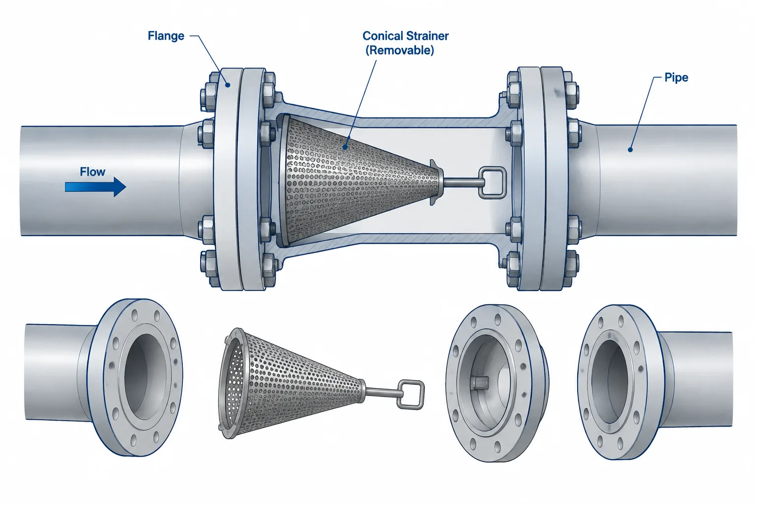
Temporary strainers create a drafting challenge because the startup arrangement and the final operating arrangement are not the same. The piping model must protect equipment during commissioning while also defining how the insert will be accessed, removed, and replaced by the approved permanent joint configuration.
This guide focuses on the coordination decisions behind temporary strainers in piping CAD. It explains how placement, orientation, flange stack-up, differential-pressure monitoring, extraction clearance, document status, and closeout should remain consistent across the design and commissioning workflow.
Temporary strainers are installed to protect equipment and piping during flushing, startup, or commissioning. They capture weld slag, scale, gasket fragments, construction debris, and other material that may remain in a system before normal operation begins. Unlike permanent Y-strainers or basket strainers, a temporary strainer is generally intended to be inspected, cleaned, and eventually removed.
That temporary status does not make the component unimportant to layout. A strainer inserted between flanges changes the joint stack-up, may require additional access, can create substantial differential pressure when loaded, and must be documented so that it is not accidentally left in service. A useful CAD model or drawing should communicate more than the strainer’s approximate shape: it should show where it belongs, how it is oriented, and what must happen after commissioning.
What Is a Temporary Strainer?
A temporary strainer is a removable screening element placed in a piping system for a limited operating phase. It is often installed near the suction or inlet of equipment that could be damaged by debris, such as a pump, compressor, control valve, meter, or heat exchanger. Its exact location should come from approved project documents and equipment requirements rather than a drafting assumption.
Common forms include:
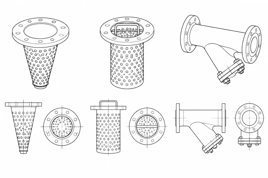
- Conical strainers: Perforated or mesh-lined elements formed into a cone and commonly installed between flanges. They are also informally called cone strainers or witch’s-hat strainers.
- Temporary basket strainers: Cylindrical or basket-shaped elements inserted into a suitable housing or flange arrangement.
- Flat screens: Disc-like screens used for particular cleaning or commissioning tasks. Their limited debris-holding area must be considered during planning.
The perforated support, mesh, reinforcing arrangement, and installation direction are design details. They should be taken from the selected strainer documentation or project standard rather than inferred from a generic CAD symbol.
Temporary vs. Permanent Strainers
| Consideration | Temporary strainer | Permanent strainer |
|---|---|---|
| Primary purpose | Startup, flushing, or commissioning protection | Continuing process protection |
| Expected service | Removed after defined acceptance criteria are met | Remains as an operating component |
| Maintenance access | Requires access to open a flange joint or designated housing | Usually has an integral cover, cap, or cleaning feature |
| Drawing treatment | Must communicate temporary status and removal requirements | Normally treated as part of the permanent line configuration |
| Model representation | May require installed and post-removal conditions | Usually represented by one operating configuration |
A temporary strainer should not be substituted casually for a permanent strainer. The two can differ in debris capacity, pressure-loss behavior, cleaning method, structural support, and suitability for prolonged operation.
Choosing and Documenting the Installation Location
The installation point must protect the target equipment while remaining accessible for inspection and removal. A location immediately adjacent to an equipment nozzle may appear logical, but it can create practical problems if the flange cannot be separated, bolts cannot be withdrawn, or nearby structures prevent removal of the screen.
During layout review, check the following:
- The protected equipment or component is clearly identified.
- The flow path does not allow debris to bypass the strainer.
- The selected joint can be opened without removing unrelated equipment.
- There is room to support the pipe while the joint is separated.
- Workers can reach the bolts and extract the strainer safely.
- Drained process fluid and trapped debris can be managed.
- The location does not conflict with insulation, platforms, guards, or structural steel.
Removal may require more space than installation. A flange joint that can be assembled in an open fabrication shop may be difficult to reopen after surrounding equipment, cable tray, insulation, and access platforms are installed.
Flow Direction and Strainer Orientation
The piping flow direction should be visible wherever a temporary strainer is shown. However, the direction in which a conical element points should not be established by a universal drafting convention. Temporary strainers are available in different configurations, and the required orientation can depend on the element construction, debris collection method, available clearance, and supplier instructions.
The CAD model, isometric, and installation note should agree on orientation. If the element is represented only by a generic symbol, add an unambiguous callout or refer to the controlled installation detail. Avoid notes such as “install in normal direction” because they do not tell fabrication or field personnel which side faces upstream.
Design review should also consider what happens when debris accumulates. The screen creates additional pressure loss, and that loss can increase as the open area becomes blocked. Process and commissioning personnel determine acceptable operating limits and inspection frequency; the CAD team should provide the connections and locations needed to implement that plan.
Differential-Pressure Monitoring
Pressure indication on each side of a temporary strainer may be used to assess blockage. Depending on the project, this could involve permanent instruments, temporary gauges, test connections, or another approved monitoring arrangement.
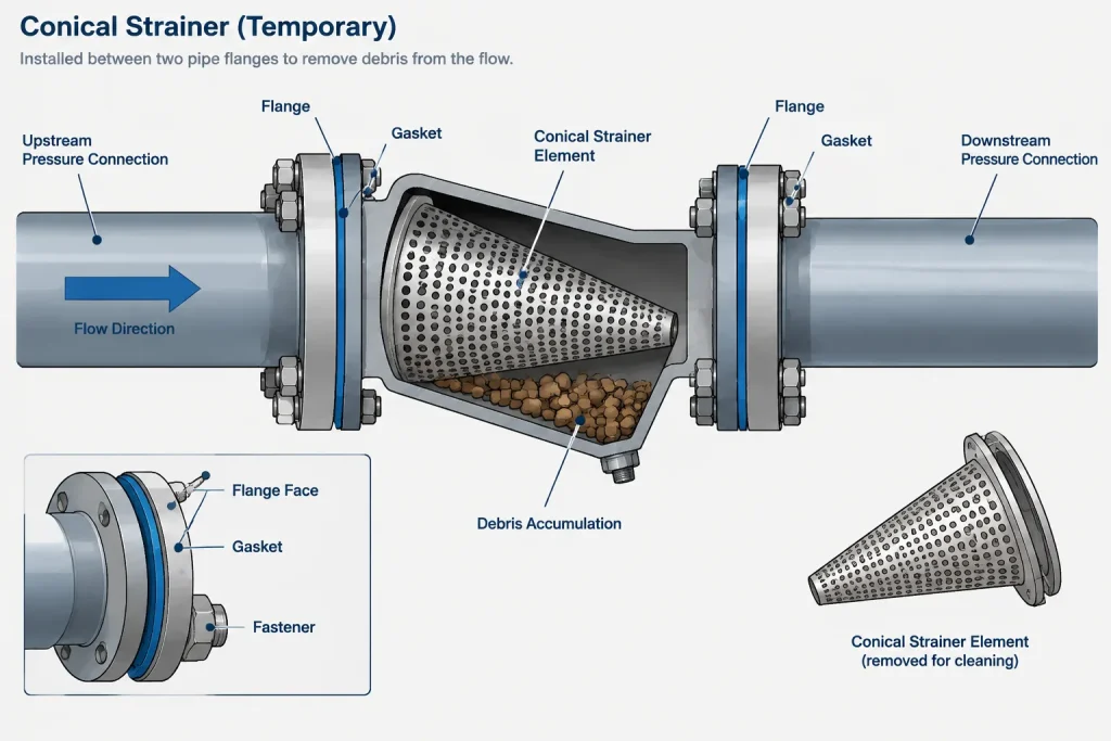
When such connections are required, verify that:
- The pressure points are actually located on opposite sides of the strainer.
- Instrument root valves and connections follow the applicable piping specification.
- Operators can read or connect the devices safely.
- The P&ID, model, isometric, and commissioning procedure describe the same arrangement.
- Temporary instruments and fittings have a defined removal or closeout disposition.
Do not add arbitrary pressure limits to a drawing. Allowable differential pressure depends on the strainer design, operating conditions, protected equipment, and approved commissioning plan.
Modeling the Flange Joint and Stack-Up
A flange-insert strainer is physically part of the assembled joint. Its rim, gaskets, and any required spacer affect the distance between flange faces. Modeling it as a zero-thickness symbol can hide a dimensional problem, especially in a tightly controlled equipment connection.
The model should use verified supplier or project dimensions when the joint stack-up affects spool length or equipment position. Check whether the assembly requires:
- A gasket on each side of the strainer rim or another specified sealing arrangement.
- Longer bolts or studs for the installed condition.
- A temporary spacer, permanent spacer, or replacement gasket after removal.
- Additional flange separation for extracting the element.
- Revised spool geometry after the temporary item is removed.
Removing the strainer does not automatically restore the joint to the correct final spacing. The permanent configuration must be defined deliberately. If a spacer replaces the temporary element, its dimensions and material must come from verified project documentation.
Representing Temporary Strainers Across Documents
P&ID
Show the temporary strainer using the project’s approved symbol and identify its temporary or startup function. Include associated pressure-monitoring connections where they are part of the process or commissioning intent. If removal changes the final configuration, a note should identify that requirement clearly.
3D model
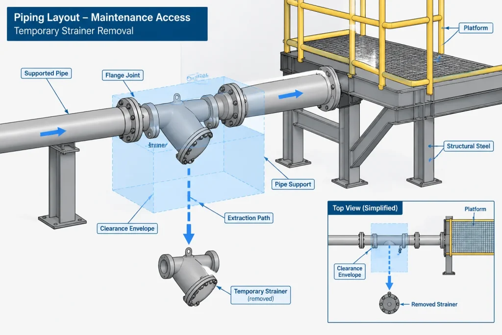
Use enough geometry to reserve joint thickness, extraction space, and maintenance access. Assign searchable status data such as temporary, commissioning, remove after flushing, or another controlled project value. Do not rely only on color, because colors may disappear in exports and printed deliverables.
Piping isometric
The isometric should identify the installation joint, flow direction, component tag or item reference, gasket arrangement, and relevant temporary-work note. The bill of materials should distinguish temporary items from permanent piping materials so procurement and field control are not confused.
Commissioning and removal records
A controlled list can track installation, inspection, cleaning, and removal. The final drawing status should reflect the permanent configuration rather than leaving an unresolved temporary component in the record model.
Removal and Maintenance Clearance
Access must account for the complete removal sequence, not merely visibility of the flange. The line may need to be isolated, drained, supported, unbolted, spread, cleaned, re-gasketed, and reassembled. Large or contaminated elements may also require lifting and containment planning.
CAD review should look for nearby obstructions in the likely extraction path. Typical conflicts include structural braces, floor edges, cable tray, instrument tubing, valve operators, insulation, and adjacent pipe runs. Where flange spreading or pipe movement is anticipated, the responsible engineering discipline must confirm that the connected equipment and supports can tolerate the planned activity.
Common CAD and Documentation Errors
- Treating the strainer as a permanent fitting: This can leave the final operating configuration undefined.
- Omitting flow direction: Field personnel cannot verify the intended installation orientation.
- Using zero-thickness geometry: Spool length and bolting conflicts remain hidden.
- Providing no removal clearance: The element becomes trapped after surrounding construction is complete.
- Failing to identify pressure points: Differential-pressure monitoring may not measure across the screen.
- Mixing temporary and permanent BOM items: Procurement, installation, and closeout records become difficult to reconcile.
- Leaving the strainer in the as-built model: The record no longer represents the verified operating arrangement.
Practical Review Checklist
- Confirm the strainer type and installation location from approved project information.
- Show flow direction and an unambiguous element orientation.
- Use verified dimensions where the insert affects the flange stack-up.
- Check gasket, bolting, spacer, and post-removal requirements.
- Provide access to open the joint and extract the element.
- Coordinate pipe supports and equipment nozzle loads during removal planning.
- Verify pressure-monitoring connections on both sides when required.
- Identify the component as temporary in the model, drawings, and BOM.
- Define who records installation, cleaning, acceptance, and removal.
- Update final documentation to show the verified permanent configuration.
A temporary strainer is a commissioning component with permanent layout consequences. Modeling its physical stack-up, access needs, monitoring points, and removal state helps protect equipment while preventing a short-term installation from becoming a long-term documentation problem.
Managing the Strainer as a Temporary Model State
A practical workflow treats the temporary strainer as a controlled configuration rather than an ordinary permanent fitting. The installed condition should show the physical insert, associated joint requirements, access envelope, and any monitoring provisions. The post-removal condition should show the approved final joint arrangement without relying on an undocumented field adjustment.
Installed condition
Model attributes and drawing notes should make the commissioning purpose searchable and visible. The representation should identify the affected flange joint, protected equipment, flow direction, and controlled orientation reference. Where the actual geometry is simplified, the reserved stack-up and extraction space should still reflect verified project information.
Removal-ready condition
Review the anticipated work sequence as a layout operation. Isolation, drainage, temporary support, bolt access, flange separation, element extraction, debris containment, and reassembly can each introduce a different space requirement. A general maintenance zone is not a substitute for checking the actual removal path.
Permanent condition
The final model should represent the verified operating arrangement after the temporary element and related temporary hardware have been addressed. Any replacement spacer, gasket arrangement, bolting change, instrument disposition, or spool revision must come from approved documentation. Closeout should also reconcile drawings, material records, commissioning records, and the record model.
Recommended Coordination Handoff
- Process or commissioning team: Defines the protective purpose, operating phase, monitoring intent, acceptance criteria, and removal authorization.
- Piping engineering: Confirms the joint arrangement, piping specification requirements, supports, flange loading considerations, and final configuration.
- Layout and CAD team: Reserves physical space, displays flow and orientation, checks access, and maintains consistent model status.
- Instrumentation team: Coordinates approved pressure-monitoring connections and the disposition of temporary devices.
- Construction and field teams: Confirm that the proposed installation and extraction sequence is practical in the completed surrounding layout.
- Document control: Ensures that temporary notes are resolved and that issued records represent the accepted permanent condition.
The central control question is not merely whether the strainer fits between the flanges. The design should also show whether it can be monitored, serviced, removed, and closed out without leaving an ambiguous piping configuration.
Frequently Asked Questions
Where should a temporary strainer be placed?
Its location should follow approved project documents and the requirements of the equipment being protected. CAD review should then confirm that debris cannot bypass the element and that the selected joint remains accessible for inspection and removal.
Which direction should a conical temporary strainer point?
There is no universal drafting assumption that applies to every design. Orientation should be taken from the selected strainer documentation, project detail, or approved installation instruction and communicated consistently in the model and drawings.
Should a temporary strainer appear in the piping bill of materials?
It should be controlled in accordance with the project material workflow, but its temporary status must be unmistakable. Separating temporary commissioning items from permanent piping materials helps prevent procurement, installation, and closeout confusion.
What should replace the strainer after removal?
The approved permanent configuration may involve a defined joint arrangement, spacer, gasket change, bolting change, or spool revision. The CAD team should not infer that configuration; it must come from verified project documentation.
Is color enough to identify a temporary strainer in a model?
No. Color can be lost in exports, printouts, neutral-file exchanges, or display changes. Use searchable component data, drawing notes, item identification, and controlled status information in addition to any visual convention.
How can removal access be checked in CAD?
Review the complete field sequence and the intended extraction path. Check access to bolts, required flange separation, pipe support needs, lifting or handling space, drainage, containment, insulation, structures, nearby piping, and other installed services.