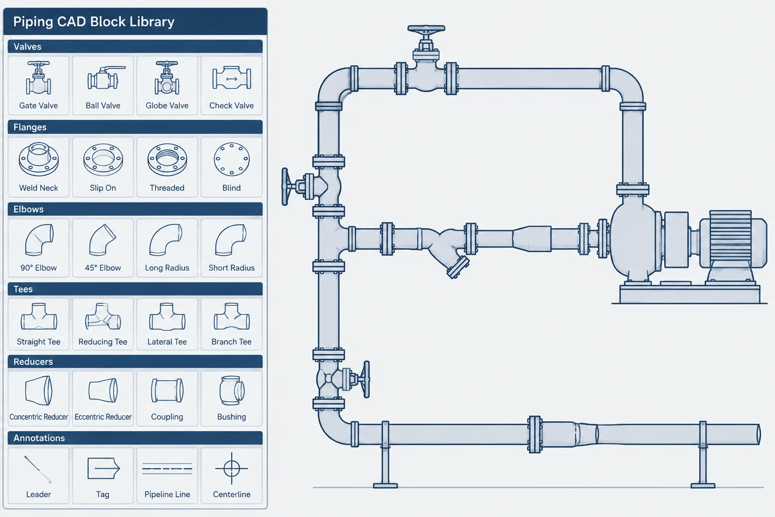
Piping CAD block library management is the discipline of making reusable drawing content easy to find, understand, verify, and update. The key challenge is not simply storing geometry. It is preserving the context that tells a user what the geometry represents, how it should be inserted, and where its limitations begin.
This guide presents a practical control workflow for schematic symbols, layout components, dimension-based blocks, fabrication details, and annotation resources. It focuses on the decisions that help prevent unit errors, inappropriate scaling, lost source information, inconsistent insertion points, and accidental reuse of superseded content.
A piping CAD block library can save drafting time, improve drawing consistency, and reduce repeated geometry creation. It can also spread errors rapidly if blocks are stored without clear units, source information, revision control, or limits on use. A well-drawn component is not automatically correct for every pipe size, specification, manufacturer, or project.
Library management therefore involves more than collecting DWG files. It requires a controlled method for classifying content, checking geometry, recording assumptions, and deciding when a block may be reused. The objective is not to make every item highly detailed. It is to provide the right representation for the drawing purpose while preserving reliable engineering information.
What belongs in a piping CAD block library?
The word block can describe several kinds of reusable content. Keeping these categories separate helps users understand what a file is intended to represent.
- Schematic symbols: P&ID symbols for valves, fittings, instruments, equipment connections, and line accessories.
- Generic 2D components: plan, elevation, or section outlines used for layout studies and general arrangement drawings.
- Dimension-based components: geometry built from verified component dimensions for a stated size, type, and connection arrangement.
- Fabrication details: more detailed views that may show welds, end preparations, joint elements, or assembly relationships.
- Annotation resources: tags, callouts, continuation markers, flow arrows, title elements, and other drafting aids.
These categories should not be treated as interchangeable. A schematic valve symbol does not establish face-to-face length. A generic valve outline may support an early layout but should not be assumed to provide a vendor-specific maintenance envelope. A fabrication detail may contain more information than is appropriate for a general arrangement drawing.
Build the library around declared purpose
Every reusable item should have a stated purpose. A short description such as “generic plan symbol,” “layout envelope,” or “dimension-controlled component” is more useful than a filename that identifies only the component type.
Purpose also determines the required verification level. A symbol intended only to communicate valve function has different checking needs from a flanged valve outline used to locate mating joints. The second item may affect pipe cut lengths, flange locations, access, and replacement planning, so its controlling dimensions require stronger verification.
Useful classification fields
| Field | What it communicates | Why it matters |
|---|---|---|
| Content type | Symbol, outline, detail, annotation, or model component | Prevents schematic content from being used as physical geometry |
| View | Plan, elevation, section, isometric, or schematic | Helps users select the correct representation |
| Units | The units in which the source geometry was created | Reduces accidental insertion at the wrong scale |
| Size basis | Nominal size, actual geometry, or size-independent symbol | Clarifies whether scaling or substitution is permitted |
| Dimensional basis | Generic, standards-based, project-based, or vendor-based | Identifies where verification must occur |
| Status | Draft, checked, released, superseded, or archived | Separates current content from unverified or obsolete files |
| Source record | The document or data used to create the item | Supports later review without implying automatic approval |
Use filenames that describe identity, not approval
A practical filename should help distinguish one library item from another without becoming a substitute for embedded metadata or a component schedule. Depending on the content, useful filename elements may include component family, connection type, nominal size designation, view, unit system, and revision.
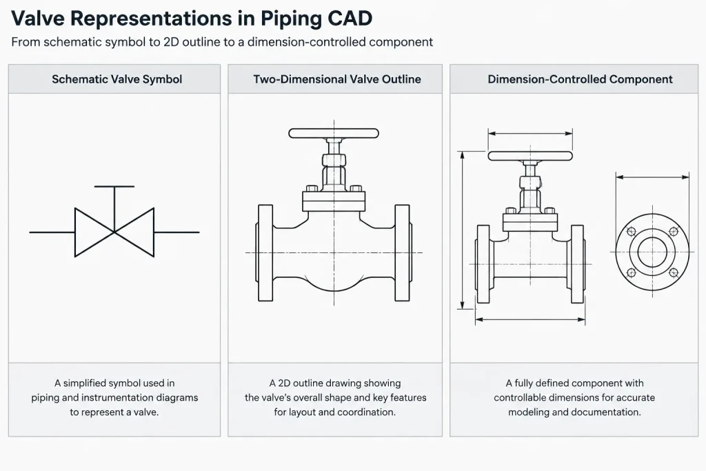
Avoid names such as “final,” “approved,” or “standard” unless those terms have a formally defined meaning within the organization. A block may be released for library use and still require project-specific checking. It is also risky to identify a generic item with a manufacturer name when the geometry was not created from current, traceable manufacturer information.
Use one naming sequence consistently. For example, do not describe one item as valve-size-view and another as view-valve-size unless there is a clear reason. Predictable naming improves search results and makes missing information easier to notice.
Control units at the file and object levels
Unit errors are among the most disruptive library problems because incorrectly inserted geometry can still look plausible at some zoom levels. The source file units, insertion behavior, and expected project units should all be documented and tested.
Do not use uniform scaling as a method for converting one nominal pipe size into another. Pipe sizes and component dimensions do not generally change according to one universal scale factor. Even when two items look similar, their face-to-face, center-to-end, bore, flange, operator, and envelope dimensions may follow different relationships.
A unit check should include a known control measurement. This does not require placing a dimension permanently in the block. The reviewer can measure a verified feature after insertion and compare it with the source record. Testing should be performed in a clean file rather than only in the source drawing where inherited settings may hide a problem.
Choose insertion points and connection references deliberately
A block origin should correspond to how the item is placed and replaced. Useful references may include a pipe centerline intersection, fitting center, flange face, valve end face, equipment nozzle center, or tag insertion point. The best choice depends on the content type.
Connection-sensitive components also benefit from clearly defined ports or reference points. For example, a reducer requires more than a convenient geometric center if users must connect pipe centerlines correctly. An elbow may need a reference based on its centerline intersection or tangent geometry. A valve used for dimensional layout should have unambiguous end-face locations.
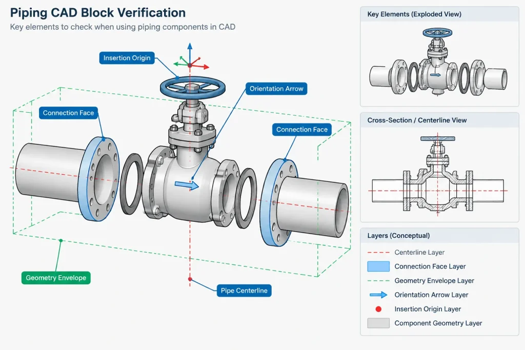
Origins should remain consistent within a component family. If similar valves use different insertion conventions, replacing one block with another can move the pipeline even when both items are individually accurate.
Keep geometry, layers, and attributes clean
Reusable content should contain only what users need. Stray objects, hidden construction geometry, unrelated text, distant entities, and duplicate linework can enlarge drawing extents or interfere with selection and plotting.
Layer behavior should follow a documented library policy. Some organizations place block geometry on neutral internal layers and control display through the insertion layer. Others use internal layers to separate centerlines, outlines, hidden features, and annotation. Either approach can work, but mixing both without rules produces unpredictable results.
Attributes and data fields should also be limited to information that can be maintained. A component tag, description, size, connection, or library identifier may be useful. Unverified fields can create false confidence, especially if they look like specification or procurement data.
Separate generic geometry from project and vendor data
A central library should normally preserve reusable content rather than silently absorb project-specific modifications. If a drafter stretches a generic block to match a selected item, that modified geometry should not automatically overwrite the master file.
Maintain clear boundaries among:
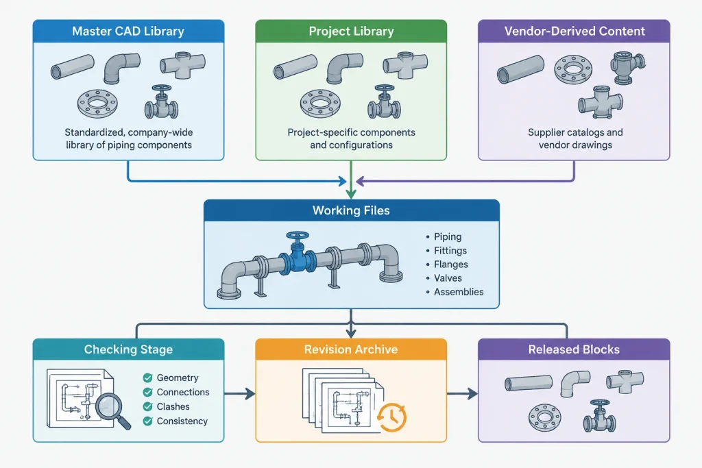
- Master library content: controlled reusable resources.
- Project library content: approved project adaptations, symbols, and specification-specific items.
- Vendor-derived content: geometry associated with a particular supplied component or package.
- Working content: temporary studies that have not completed checking.
Vendor-derived geometry should retain a traceable relationship to its source and revision. It should not be generalized to other products merely because the components share a nominal description.
Use a repeatable block verification checklist
Before releasing an item to the piping CAD block library, review both drafting quality and engineering meaning.
- Confirm the intended drawing type and level of detail.
- Verify source units and test insertion into a clean drawing.
- Check the origin, centerlines, connection points, and orientation.
- Compare controlling dimensions with the recorded source.
- Confirm that nominal size labels are not being used as actual dimensions.
- Review layers, line types, colors, and plotting behavior under the library policy.
- Remove stray geometry, duplicate objects, and unnecessary detail.
- Check attribute names, default values, and editable fields.
- Confirm that the item has a unique library identifier and revision status.
- State whether the geometry is generic, standards-based, project-based, or vendor-based.
- Record limitations, such as “symbolic only” or “maintenance envelope not included.”
Manage revisions without breaking active drawings
Updating a master block does not guarantee that every existing drawing should change. A geometry correction may be important, while a cosmetic cleanup may not justify modifying issued work. Replacement can also affect attributes, layer behavior, insertion points, and connected geometry.
Record what changed and whether the change affects dimensions, connectivity, appearance, or data. Keep superseded versions available for traceability, but separate them from the current selection area so users do not insert them accidentally.
For dimensionally significant changes, review affected project drawings rather than assuming a block redefinition is harmless. The library revision and the drawing revision are related records, not the same record.
A library is a reference, not an engineering decision
A controlled piping CAD block library makes reuse safer, but it cannot determine whether a component suits a service, pressure-temperature condition, piping specification, maintenance strategy, or purchased product. Those decisions depend on project documents and verified component data.
The most reliable library communicates both what each item contains and what it does not contain. When purpose, units, dimensional basis, origin, source, and revision are visible, drafters can reuse content efficiently without mistaking convenient geometry for project approval.
Turn library control into a routine drafting workflow
A library policy becomes useful only when it fits the way content is requested, created, reviewed, released, and revised. New geometry should enter a working area first, with its purpose and source recorded before detailed cleanup begins. This prevents an attractive but poorly documented block from reaching the shared library merely because it appears complete.
Assign responsibility at each stage
The person who creates a block may understand its geometry but may not have authority to approve its dimensional basis or project use. A practical workflow distinguishes drafting review from engineering or project review. Drafting review addresses units, origin, layers, attributes, object quality, and insertion behavior. Technical review addresses the source, controlling dimensions, intended representation, and stated limitations.
Release authority should also be clear. Without an identified library owner, users may overwrite master content, create competing versions, or treat a personal working file as the current reference.
Use a release record that travels with the item
A released item should remain understandable when separated from the person who created it. Its record should identify the content type, intended view, unit basis, dimensional basis, source, revision status, and known limitations. The record may be maintained through block attributes, file properties, a catalog entry, or another controlled system, provided users can locate it reliably.
Descriptions should state what was checked rather than relying on broad approval language. For example, a release record can distinguish a geometry and insertion check from project-specific acceptance. This helps prevent library status from being mistaken for confirmation of material, service, rating, specification, or procurement suitability.
Test retrieval as well as geometry
A technically correct block has limited value if users cannot identify it or distinguish it from similar content. Periodic library reviews should test search terms, naming consistency, preview clarity, category placement, and visibility of superseded items. Duplicate blocks with slightly different names should be reconciled or clearly differentiated.
Library maintenance should also include feedback from active drawings. Repeated insertion problems, manual corrections, missing views, or misunderstood attributes are signs that the library item or its documentation needs review. Corrections should return through the controlled revision process rather than being made silently in the master file.
Practical release principle
The strongest release question is not simply whether a block is accurate. Ask whether another user can determine its purpose, source, units, placement method, verification status, and limitations without relying on undocumented knowledge. If that context is missing, the item is not ready for dependable reuse.
Frequently asked questions
Should every piping component be stored as a CAD block?
No. Reuse is most valuable when the representation has a recurring purpose and can be controlled consistently. One-time studies, incomplete vendor geometry, and temporary project concepts are better kept in working or project locations until their status is clear.
Can a released block be used on any project?
No. Release indicates that the item has passed the organization’s library process; it does not establish suitability for every piping specification, service, purchased component, or project requirement. Project documents and verified component information remain controlling.
Is a nominal size label enough to verify geometry?
No. A nominal designation identifies a size category but should not be treated as an actual measured dimension. Dimension-sensitive blocks require comparison with the recorded dimensional source.
Should users edit a master block to match project conditions?
Users should not silently overwrite controlled master content. A project-specific adaptation should be stored and identified separately, then reviewed under the applicable project process. A broadly useful correction can be submitted for controlled revision of the master item.
How should obsolete blocks be handled?
Superseded content should remain available when traceability is required, but it should be separated from current selection tools and marked clearly. This preserves the history of older drawings without encouraging accidental insertion into new work.
What is the difference between a generic outline and a vendor-derived block?
A generic outline communicates an approximate or commonly useful representation without claiming to match a purchased product. A vendor-derived block is associated with traceable product information and should retain that source context. Neither should be substituted for the other without verification.