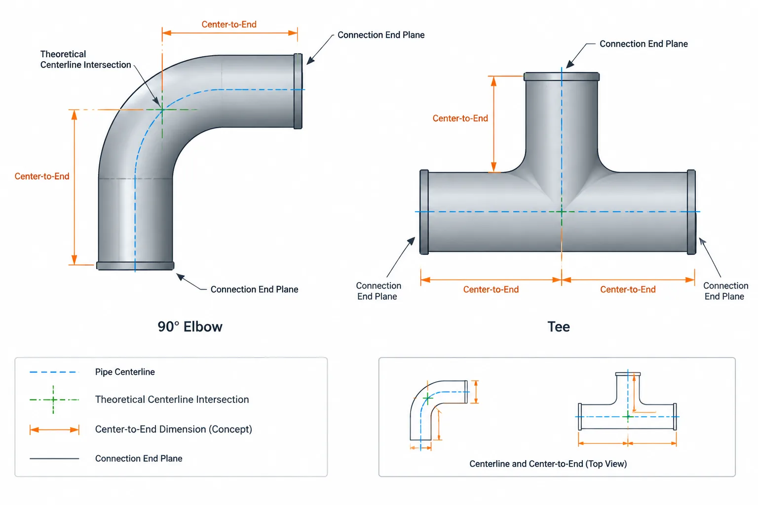
Pipe fitting center-to-end dimensions define the relationship between routing centerlines and actual connection planes. In CAD, that relationship affects component placement, pipe termination, branch stations, spool dimensions, and the consistency of piping isometrics.
This guide explains how to identify the correct geometric reference, distinguish fitting takeout from pipe cut length, and use verified port locations instead of relying on the visible outline of a CAD block or solid.
Pipe fitting center-to-end dimensions are among the most important reference values in piping layout. They determine where a fitting begins and ends relative to its centerline geometry, which directly affects pipe cut lengths, branch locations, equipment connections, and spool dimensions.
The concept appears simple, but errors occur when designers measure from the wrong reference point, substitute a nominal envelope for a connection dimension, or assume that every fitting uses the same dimensioning convention. A reliable CAD workflow starts by identifying the fitting type, its connection ends, and the exact geometric points controlled by the applicable dimensional reference.
What Is a Center-to-End Dimension?
A center-to-end dimension is the distance from a defined fitting center to the connection end of that fitting. The meaning of the center depends on the component:
- For an elbow, it is generally measured from the theoretical intersection of the connected pipe centerlines to an end of the elbow.
- For a tee, it is measured from the intersection of the run and branch centerlines to a run or branch end.
- For a cross, it is measured from the common centerline intersection to each connection end.
- For some flanged fittings, the controlled point may be a flange face rather than a weld end.
The connection end must also be understood correctly. It may be a butt-weld end, socket-weld end, threaded end, flange face, or another defined termination. The physical edge visible in a simplified CAD block is not automatically the correct dimensional endpoint.
Common Fitting Dimension Conventions
Not every fitting is described primarily by center-to-end dimensions. The appropriate convention follows the component geometry and the way it connects to adjacent piping.
| Component | Common controlling convention | Typical CAD use |
|---|---|---|
| Elbow | Center-to-end | Locates both connection ports from the theoretical centerline intersection |
| Tee | Center-to-end for run and branch | Controls run continuation and branch takeoff location |
| Cross | Center-to-end in multiple directions | Locates the four connection ports around a common center |
| Reducer | End-to-end | Controls the axial length between large and small ends |
| Cap | End-to-crown or overall length convention | Defines the projection beyond the connected pipe end |
| Coupling | Overall or end-to-end length | Controls the axial envelope and connection locations |
| Flanged fitting | Center-to-face or face-to-face, depending on form | Locates gasket contact faces rather than weld-end planes |
These descriptions are conceptual rather than substitutes for a verified dimensional table. The applicable piping standard, project specification, component class, size, end connection, and manufacturer information must be checked before assigning a final value.
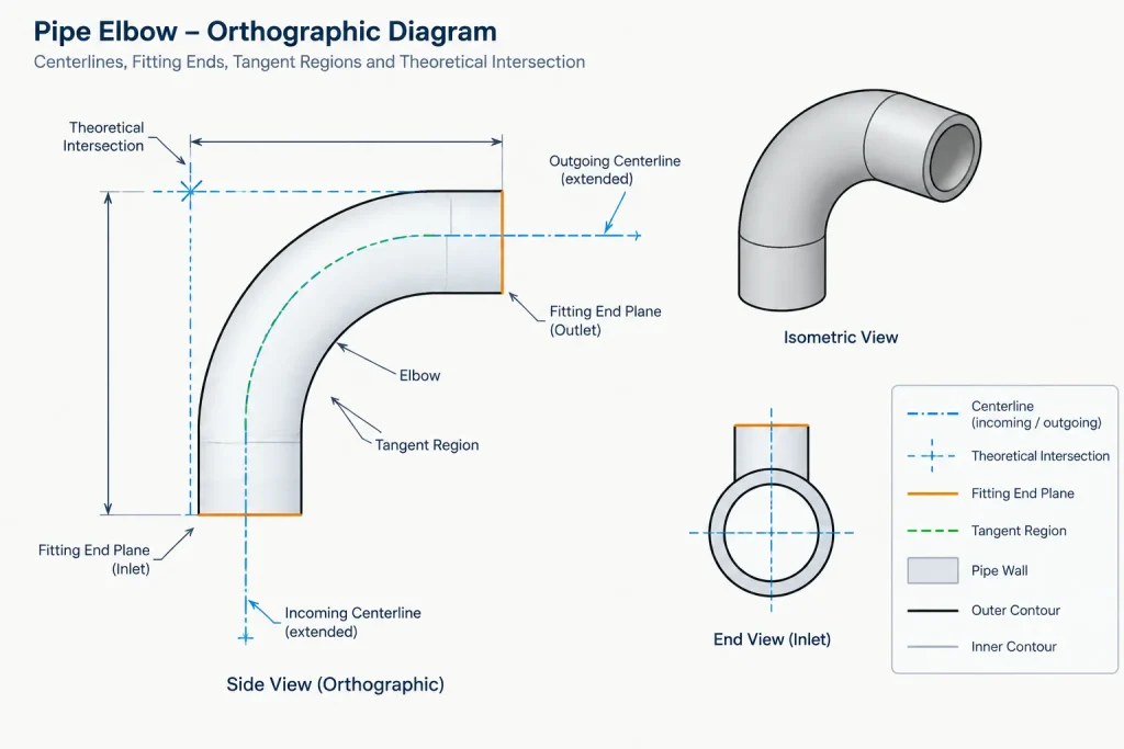
Elbow Center-to-End Geometry
For a conventional elbow, the center-to-end dimension is tied to the theoretical intersection of the incoming and outgoing pipe centerlines. This intersection is often outside the actual material of the fitting. It is a geometric construction point, not necessarily a point that can be physically marked on the elbow.
In CAD, the elbow can be represented by two ports located on the connected centerlines. Extending those centerlines until they intersect establishes the theoretical intersection. The distance from that point to each fitting end defines the layout takeout for a symmetrical elbow.
This reference should not be confused with the elbow tangent points. Tangent points describe where the curved centerline transitions into straight portions of the fitting geometry. Depending on the representation and fitting form, a tangent point and an end plane are not interchangeable.
Why elbow takeout matters
If two straight pipe runs meet at an intended corner, the pipe cannot normally extend all the way to the centerline intersection. The elbow occupies part of each leg. The designer therefore subtracts the applicable fitting takeout from the controlled centerline geometry when determining adjacent straight-pipe lengths.
A common modeling error is to draw pipe to the corner and place an elbow over it without trimming the straight segments. The route may look correct in plan, but the resulting pipe lengths and connection ports overlap.
Tee Run and Branch Dimensions
A tee has at least two distinct directional relationships: the run and the branch. The center is the theoretical intersection of their centerlines. Distances from that center to the run ends may differ from the distance to the branch end, depending on the fitting type and size combination.
For a reducing tee, the branch size or one of the run sizes changes, so a designer should not assume that the geometry is identical to an equal tee with a resized port. The correct component record must carry both the connection sizes and the corresponding dimensional data.
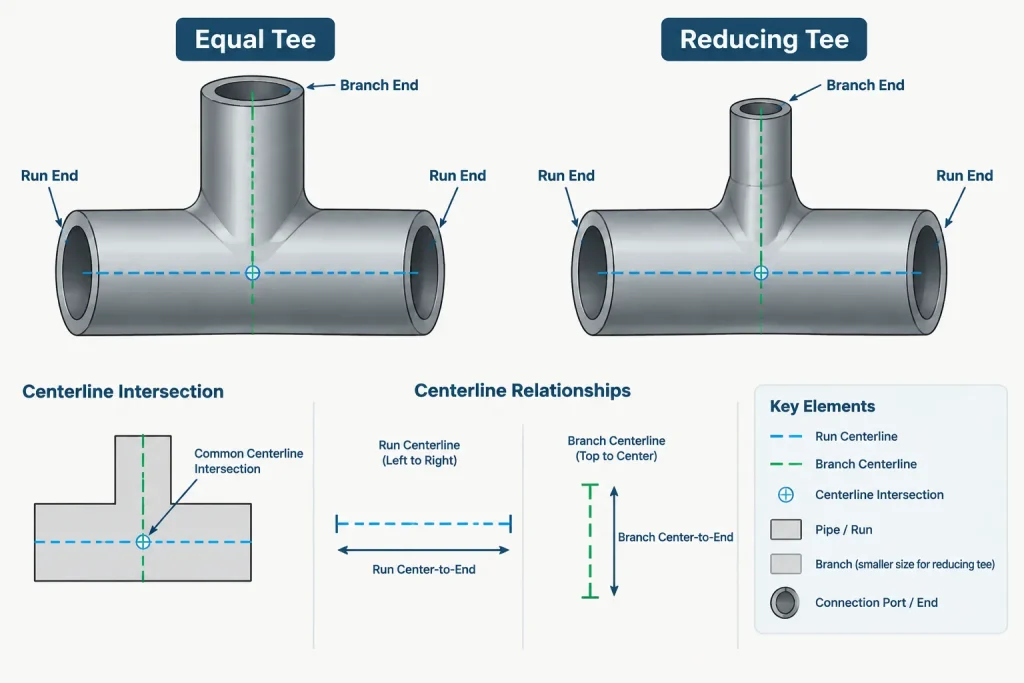
In a CAD model, the tee origin is often placed at the centerline intersection. That can be convenient because the branch station remains stable if the component is replaced. However, the ports still need verified offsets from that origin. A tee block with visually plausible geometry but incorrect port positions can shift every connected spool dimension.
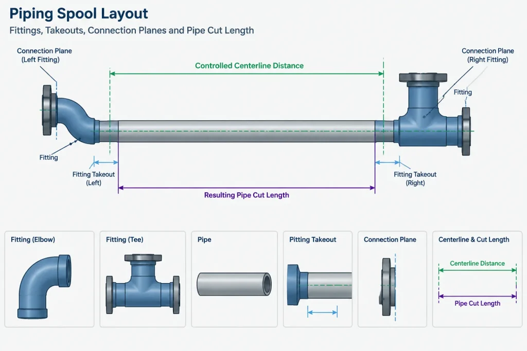
Center-to-End Is Not the Same as Cut Length
Center-to-end dimensions describe the fitting. Cut length describes a piece of pipe or, in some fabrication contexts, the prepared length of a component. They are related but not equivalent.
To determine a straight pipe cut length between two fittings, the workflow generally begins with the controlled distance between fitting centers, faces, or other layout references. The appropriate fitting takeouts are then accounted for at both ends. Additional considerations may include:
- Connection type and engagement
- Weld-end preparation
- Socket insertion requirements
- Thread makeup assumptions
- Gasketed joint faces
- Field-fit or trim allowances authorized by the project
- Fabrication tolerances and measurement practices
Because these factors vary, a center-to-end value should not be treated as a complete fabrication instruction. The drawing must make clear whether a dimension controls centerlines, component ends, flange faces, or actual pipe cut ends.
Nominal CAD Geometry vs. Verified Component Geometry
Generic fitting geometry is useful during routing studies, preliminary layouts, and clearance checks. It becomes risky when an unverified block is used to generate spool dimensions or material reports.
A sound component record should distinguish between:
- Nominal size: the named connection size, not a measured fitting length.
- Connection definition: butt-weld, socket-weld, threaded, flanged, or another end type.
- Dimensional source: the controlled standard, project library, or verified manufacturer record.
- Port locations: the coordinates and directions used to connect pipe centerlines.
- Graphical envelope: the body shape used for display and interference checking.
The ports and the visible solid should agree, but they serve different purposes. Port coordinates control connectivity and dimensions. The graphical envelope supports visualization and clearance review. Increasing an envelope to show insulation or clearance does not change the fitting’s connection dimensions.
A Practical CAD Placement Workflow
- Confirm the fitting identity. Verify size combination, fitting form, material class, schedule or bore requirements where applicable, and end connections.
- Select the dimensional basis. Use the project-approved reference rather than measuring a catalog image or scaling a drawing.
- Establish the centerline geometry. Define the pipe axes, intersection, branch station, and required angle before placing detailed solids.
- Place the component origin. Use a consistent origin such as the theoretical centerline intersection or a documented primary port.
- Locate every port. Apply the correct center-to-end, center-to-face, or end-to-end relationship for each connection.
- Connect and trim straight pipe. Terminate pipe at the fitting ports rather than allowing centerline construction geometry to determine cut ends automatically.
- Check dimensions independently. Measure between actual modeled endpoints and compare the result with the intended layout chain.
- Preserve source metadata. Record whether the component is generic, standards-based, project-specific, or manufacturer-specific.
Drawing and Model Review Checks
Reviewers should look beyond the visible fitting shape. Useful checks include:
- Do connected pipe centerlines intersect at the intended theoretical point?
- Are the fitting ends normal to the connected pipe axes?
- Does a reducing tee use the correct port sizes and offsets?
- Are flange dimensions taken to the correct faces?
- Have pipe lengths been measured between connection planes rather than block extents?
- Do the isometric dimensions agree with the model’s fitting ports?
- Has a generic component been mistaken for verified fabrication geometry?
- Will replacing the fitting with another approved component preserve the intended branch or face location?
Using Dimension Tables Responsibly
Dimension tables are most useful when their scope is understood. Before applying a listed center-to-end value, confirm that the table covers the correct fitting family, size, angle, end type, and dimensional series. Similar-looking components can follow different conventions.
Do not derive missing sizes by proportionally scaling another fitting. Nominal pipe sizes are not a linear geometric scale, and dimensional series may change relationships across the size range. Likewise, a manufacturer-specific valve or specialty fitting should not be replaced by a generic standardized envelope without checking the required face and port locations.
Key Takeaway
Pipe fitting center-to-end dimensions connect abstract routing centerlines to real component endpoints. Used correctly, they support accurate fitting placement, branch positioning, pipe cut-length calculations, and spool documentation. Used incorrectly, they can create overlaps, gaps, shifted nozzles, and inconsistent isometrics even when the model looks visually acceptable.
The safest approach is to model from defined reference points, maintain verified port data, and state clearly whether dimensions are center-to-end, center-to-face, face-to-face, or end-to-end. That discipline makes piping CAD geometry easier to review, replace, and fabricate.
Reference Hierarchy for CAD and Drawing Control
When several representations disagree, the fitting should not be positioned by whichever outline looks most convincing. The controlling basis should come from the project-approved dimensional source and the defined connection references. A catalog image, schematic symbol, clearance envelope, or simplified block may communicate shape without accurately locating the connection planes.
A practical reference hierarchy begins with the component identity and end-connection definition. The applicable dimensional record establishes the port offsets, while project requirements determine how those ports relate to equipment nozzles, adjacent fittings, and controlled layout coordinates. The visible body geometry should then be checked against the ports rather than used to create them.
Separating Routing Geometry from Fabrication Geometry
Routing centerlines establish direction, intersection points, and branch stations. Fabrication geometry establishes where material ends, where joints occur, and how components connect. These layers are related, but they should remain distinguishable in the model.
- Centerline geometry controls the intended piping path and theoretical intersections.
- Component ports define connection locations, orientations, and end types.
- Body geometry represents the fitting envelope for display and interference review.
- Fabrication dimensions communicate the controlled distances needed for spool preparation and assembly.
Keeping these functions separate makes errors easier to diagnose. If the route is correct but the pipe ends overlap, the problem may be an incorrect port offset. If the ports connect correctly but the fitting clashes with nearby objects, the body envelope or selected component may require review.
Managing Component Replacement
A well-structured CAD model allows a fitting to be replaced without silently moving a controlled branch, equipment interface, or flange face. Before substitution, identify which reference must remain fixed. Depending on the layout, that reference may be a centerline intersection, branch station, connection plane, or equipment interface.
After replacement, recheck every port rather than assuming that a similar fitting has identical takeout. Confirm connected pipe endpoints, fitting orientation, dimensional chains, and any downstream geometry that depends on the changed component.
Recommended Handoff Information
When a model or drawing is issued for review, the component data should make its dimensional status clear. Useful records include the fitting description, connection types, dimensional source, component origin, port definitions, and whether the geometry is generic or verified for the intended specification.
This information helps reviewers distinguish a routing placeholder from fabrication-controlled geometry. It also reduces the risk that a visually complete model will be treated as dimensionally approved before its fitting data has been checked.
Frequently Asked Questions
Where is the center of an elbow for center-to-end measurement?
It is generally the theoretical intersection of the connected pipe centerlines. That construction point may lie outside the physical fitting and should not be confused with a tangent point or visible body edge.
Can the edge of a CAD fitting block be used as the connection endpoint?
Only if the block has been verified and its edge is intentionally aligned with the defined connection plane. Simplified graphics and clearance envelopes may extend beyond or stop short of the actual port.
Is fitting takeout the same as straight-pipe cut length?
No. Takeout describes how the fitting occupies the controlled layout geometry. Pipe cut length must also reflect the references at both ends, connection behavior, joint requirements, and applicable fabrication practices.
Why can a tee require different run and branch offsets?
The run and branch are separate directional relationships measured from the centerline intersection. Their offsets depend on the selected fitting geometry and should come from the verified component record rather than visual symmetry.
Should a generic fitting be used for spool dimensions?
Not unless its port locations and dimensional basis have been verified for the required component. Generic geometry is useful for routing and visualization, but it should not automatically be treated as fabrication-controlled data.
What should remain fixed when replacing a fitting in CAD?
That depends on the design intent. The controlled reference could be a branch station, centerline intersection, flange face, equipment connection, or another interface. Identify that reference before replacement and then recheck all affected ports and dimensions.