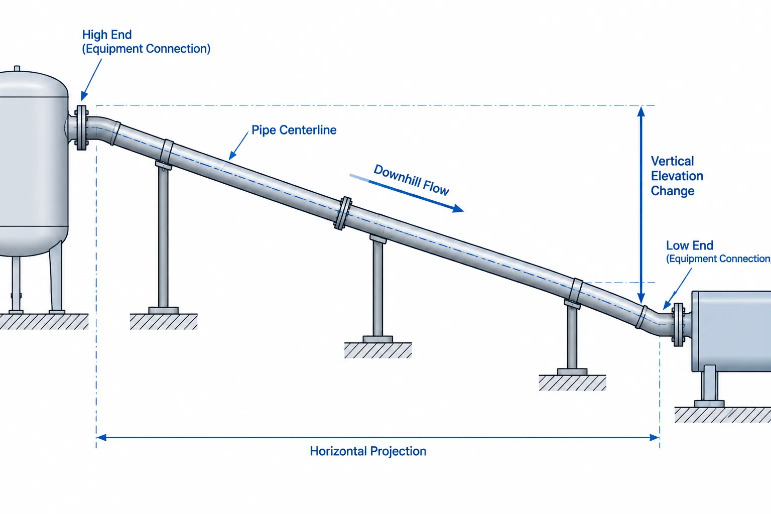
Piping slope in CAD must be controlled as three-dimensional geometry, not merely shown as a note or an angled line. The endpoint elevations, horizontal route, selected pipe datum, fitting orientation, and direction of fall must describe the same design intent.
This guide explains how to establish sloped piping from fixed interfaces, distinguish projected run from true pipe travel, coordinate components and supports, and check that plans, sections, isometrics, and model data remain consistent.
Sloped piping looks simple on a drawing: one end is higher than the other. In a CAD model, however, the slope affects coordinates, pipe length, fitting orientation, support elevations, branch connections, equipment interfaces, and fabrication dimensions. A line can appear to fall in the correct direction while still having an incorrect endpoint elevation or an ambiguous controlling datum.
A reliable piping slope workflow starts by defining what must drain, which direction it must fall, and which pipe surface or centerline controls the elevation. The model should then preserve that intent through plans, sections, isometrics, and material takeoffs.
What piping slope means
Piping slope, grade, pitch, and fall are related terms describing a vertical change over a horizontal distance. Project documentation may express the requirement as a ratio, percentage, angle, or vertical change per unit of horizontal run. These formats describe the same geometric concept, but they should not be mixed casually because rounding and interpretation can produce different endpoint elevations.
The basic relationship is:
Slope = vertical change divided by horizontal run
When slope is expressed as a percentage, the ratio is multiplied by one hundred. When it is expressed as an angle, the angle is derived from the relationship between vertical change and horizontal run. For layout work, endpoint coordinates and elevations are often more useful than an angle alone.
Direction must also be stated. A slope value without a fall arrow, flow direction, endpoint elevations, or a written direction can be interpreted two ways.
Choose the controlling pipe datum
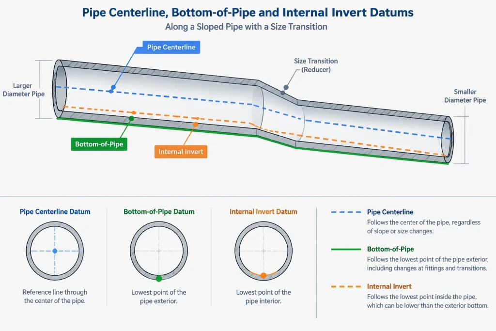
Before routing the line, identify which datum controls its elevation. Common choices include pipe centerline, bottom of pipe, invert, or a defined connection point. These references are not interchangeable.
| Datum | Typical use | Important CAD consideration |
|---|---|---|
| Pipe centerline | General piping layout and component placement | Convenient for routing, but may not directly describe the drainage surface |
| Bottom of pipe | Clearance, support, and external envelope control | Depends on actual outside diameter and changes when nominal size changes |
| Invert | Gravity-flow and drainage systems | Represents the internal low point and depends on inside diameter |
| Connection point | Equipment nozzles, package interfaces, and tie-ins | The fixed interface may control the slope calculation for the entire run |
For a straight pipe with constant outside diameter and wall thickness, its centerline, bottom surface, and invert follow parallel paths. At a size or wall-thickness transition, that relationship changes. A reducer can preserve centerline alignment, an external surface, or an internal drainage surface depending on its geometry and orientation. The designer should not assume that a continuous centerline automatically creates a continuous invert.
Start with fixed endpoints and design intent
Most sloped runs are constrained by at least one fixed point, such as an equipment nozzle, trench connection, header branch, floor penetration, or existing tie-in. Some have fixed elevations at both ends. Others have one fixed elevation and a required slope that determines the opposite elevation.
Before modeling, record:
- The required direction of fall.
- The slope format used by the project.
- The controlling datum.
- The fixed endpoint coordinates and elevations.
- Any minimum or maximum elevations caused by structure, access, or equipment.
- Locations where size changes, branches, valves, or removable items interrupt the run.
If both endpoint elevations are fixed, calculate the resulting slope and compare it with the design requirement. If one endpoint and the slope are fixed, calculate the other endpoint rather than estimating it graphically.
Horizontal run is not the same as true pipe length
A common error is to treat the plan distance as the physical length of sloped pipe. The plan distance is the horizontal projection. The pipe centerline follows the hypotenuse formed by the horizontal run and vertical change.
The centerline travel can be checked using:
True length = square root of horizontal run squared plus vertical change squared
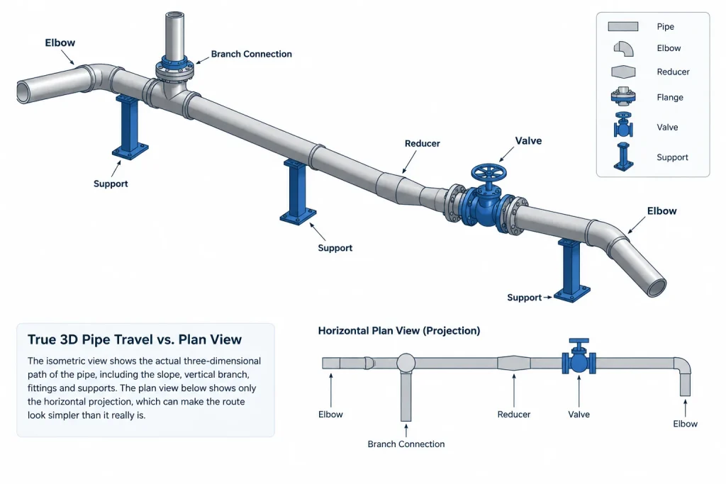
For shallow slopes, the difference may look small on a plan, but it can still affect cut lengths, spool dimensions, and accumulated coordinates. CAD geometry should provide the true three-dimensional distance. A manually prepared takeoff should not substitute a projected dimension for that length.
Fitting takeouts and end preparations must still be considered when converting centerline travel into pipe cut length. The measured distance between modeled connection points is not automatically the length of the straight pipe piece.
A practical CAD modeling workflow
1. Establish the horizontal route
Lay out the route in plan using verified equipment, structure, and interface coordinates. Identify where direction changes occur and whether elbows will remain in vertical planes or require compound orientation.
2. Assign endpoint elevations
Apply elevations to the controlling points. Keep full working precision in the model even if displayed annotations use a shorter format. Premature rounding can create small elevation disagreements across a long run or through several connected segments.
3. Create the sloped centerline
Connect the verified endpoints in three dimensions. Confirm that the line falls in the intended process direction. Do not rely only on the appearance of an isometric view, because view orientation can make a rising line appear to fall.
4. Place fittings using actual connection geometry
Elbows, tees, reducers, valves, and flanges should connect through defined ports or centerline points. A fitting inserted only by visual alignment may introduce a short level segment, an unintended offset, or a mismatch between adjoining axes.
5. Review branches and local high or low points
A branch from a sloped header inherits the header connection elevation at its actual station. Copying a branch assembly from another location without updating its elevation can produce a disconnected or distorted model. Review whether branch geometry creates a pocket, whether that pocket is acceptable, and whether a drain or vent function has been addressed by the responsible discipline.
6. Coordinate supports and penetrations
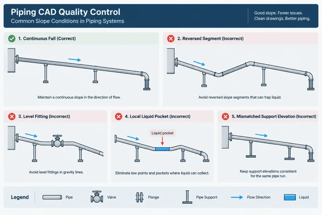
Support elevations vary along a sloped run. Reusing one support elevation for every location can force the pipe level or create unrealistic gaps. Wall sleeves, floor openings, and structural crossings should be checked against the pipe envelope at the exact crossing station, not against a nearby elevation note.
How reducers and fittings affect drainage
A sloped centerline alone does not guarantee a continuously draining internal path. Reducer orientation, valve body cavities, branch geometry, and fitting construction can create local retention points.
At a size transition, determine whether the design intent is to preserve centerline alignment, bottom-of-pipe continuity, or invert continuity. The correct choice depends on service requirements, piping specifications, component availability, and project criteria. CAD should document the selected orientation rather than leaving it to visual inference.
Elbows also deserve attention. A nominally horizontal turn within a sloped run is not necessarily flat in three-dimensional space. The entering and leaving segments may require a fitting orientation that maintains both plan direction and grade. If the route changes slope at the elbow, identify the intended break rather than forcing a fitting between misaligned axes.
Drawing and annotation practices
Sloped piping should be understandable without rotating or interrogating the model. Depending on the deliverable, useful annotations include:
- A fall arrow showing the downhill direction.
- The slope or grade in the project-approved format.
- Centerline, bottom-of-pipe, or invert elevations at meaningful control points.
- Explicit elevations at tie-ins, nozzles, penetrations, branches, and slope changes.
- A note identifying the controlling datum when it is not obvious.
- Coordinates or dimensions that establish the horizontal locations of endpoints.
A plan view communicates routing well but may not show vertical change clearly. Sections and isometrics are better for confirming elevations and fall direction. These views should agree with the model rather than contain independently adjusted dimensions.
Common sloped-piping CAD errors
- Using the wrong run: Calculating vertical change from true pipe length instead of horizontal projection.
- Omitting the fall direction: Showing a slope magnitude without indicating which endpoint is lower.
- Mixing elevation datums: Comparing a centerline elevation at one point with a bottom-of-pipe elevation at another.
- Ignoring diameter changes: Assuming a size transition preserves the invert because the centerlines align.
- Rounding each segment: Applying rounded elevation changes repeatedly and creating cumulative error.
- Measuring only in plan: Reporting projected length as pipe travel or cut length.
- Leaving fittings level: Sloping straight pipe while valves or fittings remain aligned to a horizontal axis.
- Not updating supports: Copying supports along the run without recalculating their contact elevations.
Final review checklist
- Confirm the required slope against the governing project documents.
- Verify the downhill direction and intended flow or drainage path.
- Check which datum controls each elevation.
- Recalculate endpoint elevations from horizontal run and vertical change.
- Measure true three-dimensional travel independently.
- Inspect reducers, branches, valves, and elbows for local pockets.
- Check support, structure, penetration, and equipment interfaces.
- Compare model geometry with plans, sections, isometrics, and annotations.
- Ensure displayed rounding does not alter the underlying model geometry.
The goal is not merely to draw a pipe at an angle. A dependable piping slope model establishes a traceable relationship among route coordinates, elevation datums, component geometry, and drainage intent. When those relationships are explicit, downstream drawings, support layouts, spool development, and field checks become much easier to coordinate.
Managing slope through design changes
Sloped piping should be rechecked whenever routing, pipe size, component selection, or an interface elevation changes. Moving one endpoint can affect the grade of the full run, while inserting a fitting or valve can alter connection locations and available straight-pipe length.
A sound revision process begins with the controlling constraints rather than manually adjusting nearby geometry until the model appears connected. Reconfirm the fixed endpoint, controlling datum, horizontal route, and required fall direction. Then regenerate or revise the affected geometry and inspect downstream branches, supports, penetrations, and annotations.
Model checks should use independent evidence
A visual review is useful but should not be the only check. Compare model coordinates and endpoint elevations with the displayed grade notation, then review the route in a view that clearly reveals vertical change. Measuring the three-dimensional centerline travel provides another check that the model is not reporting only a plan projection.
Component connections also require local inspection. Confirm that adjoining ports share the intended axis, that reducers preserve the selected datum, and that valves or fittings have not introduced level sections or unintended pockets. Where the drainage path depends on internal geometry, the centerline view alone may be insufficient.
Keep model geometry and drawing notes synchronized
Slope annotations should report the modeled condition rather than act as independent drafting instructions. If geometry changes, associated elevations, fall arrows, grade labels, support information, and interface notes should be reviewed together.
This coordination is especially important when different deliverables emphasize different information. A plan may establish horizontal routing, a section may communicate elevation, and an isometric may show fabrication relationships. All should trace back to the same model geometry and controlling datum.
Frequently asked questions
What should control the elevation of a sloped pipe?
The controlling datum should be defined by the design intent. It may be the pipe centerline, bottom of pipe, invert, or a fixed connection point. The selected reference must be used consistently when calculating and annotating elevations.
Why is a slope value incomplete without a direction?
The same slope magnitude can describe a line falling in either direction. A fall arrow, flow direction, written instruction, or clearly identified endpoint elevations removes that ambiguity.
Can plan distance be used as sloped pipe length?
No. Plan distance is the horizontal projection of the route. The sloped centerline follows a three-dimensional path, and fitting takeouts or end preparations must also be considered before determining a straight-pipe cut length.
Does a continuous centerline guarantee a continuous invert?
Not when pipe size or wall thickness changes. A transition may preserve centerline alignment without preserving the internal low point. Reducer geometry and orientation must be reviewed against the required drainage path.
Why can a sloped line still fail a model review?
The line may fall visually while having an incorrect endpoint elevation, mixed datums, disconnected component ports, an unintended level fitting, or unsupported annotation. Reliable review combines geometry, coordinates, elevations, component orientation, and drainage intent.
When should a sloped piping route be rechecked?
Recheck it after changes to routing, endpoint elevations, pipe size, fittings, valves, branches, supports, penetrations, or connected equipment. Each change can affect grade, true travel, clearances, and drawing annotations.