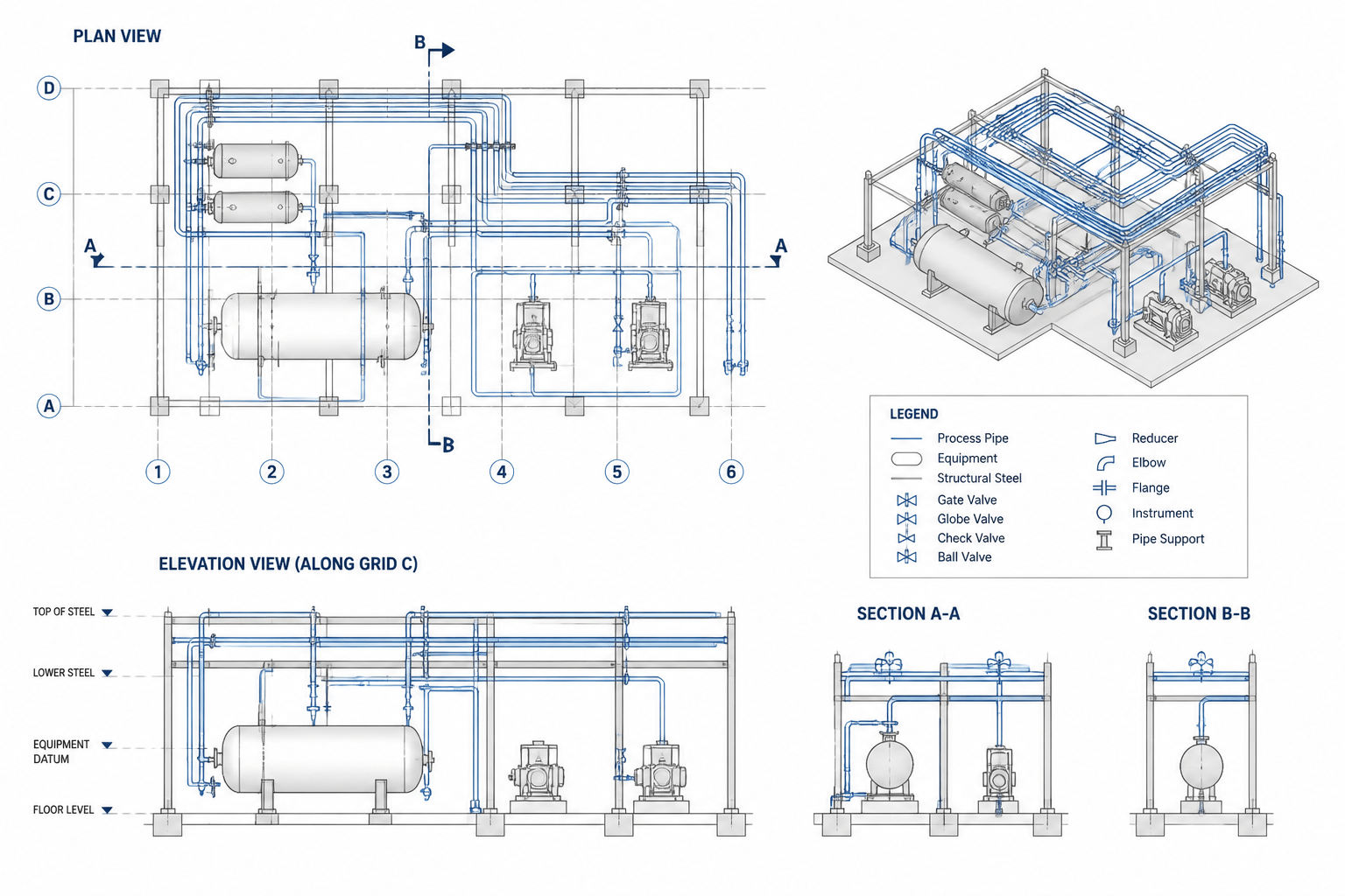
Piping general arrangement drawings are the spatial coordination layer of a plant design. They help reviewers understand how equipment, pipe routes, structures, access areas, and interfaces fit together before detailed modeling or fabrication documentation is developed.
The most reliable way to read a piping GA drawing is to separate confirmed information from graphical suggestion. Orientation, coordinates, elevations, view direction, tags, and continuation references often carry more authority than the apparent shape or spacing of a line on the sheet.
Piping general arrangement drawings provide the spatial view that connects process intent with the physical plant. They show where piping runs in relation to equipment, structures, access areas, platforms, roads, and other systems. Unlike a detailed isometric, a general arrangement drawing is not primarily a fabrication document. Its purpose is to communicate layout, coordination, and design intent clearly enough for multiple disciplines to review the arrangement.
Reading these drawings effectively requires more than following a pipe centerline. You must understand the view direction, coordinate system, elevation references, equipment orientation, continuation symbols, and the relationship between graphical information and written callouts. This guide presents a practical method for reviewing piping general arrangement drawings before detailed modeling, drafting, or field coordination.
What a piping general arrangement drawing shows
A general arrangement drawing typically combines several types of information:
- Equipment locations and identification tags
- Pipe routing through the plant or facility
- Pipe racks, sleepers, platforms, structural steel, and access ways
- Major valves, specialty items, instruments, and inline components
- Plan, elevation, and section views needed to understand the layout
- Coordinates, elevations, grid references, and drawing match lines
- References to related drawings, line numbers, and continuation areas
The drawing may be prepared for an area, unit, building, rack segment, or equipment group. Its boundaries should be established before review. A pipe that appears to stop at the edge of the sheet may continue on another drawing, connect to equipment, or terminate at a defined interface. The sheet border alone does not establish the physical end of a line.
Start with the drawing frame and orientation
Before examining individual pipes, inspect the title block, drawing number, area description, revision status, scale note, orientation symbol, and coordinate references. Confirm whether the view uses plant north, project north, or another project-defined orientation. Do not assume that the top of the sheet represents north.
Next, identify the principal grid lines or coordinate axes. Structural grids can help locate equipment and supports, but they are not substitutes for actual coordinates. When a layout must be transferred into a CAD model or checked against another discipline, use the stated coordinate and elevation information rather than measuring from the printed page.
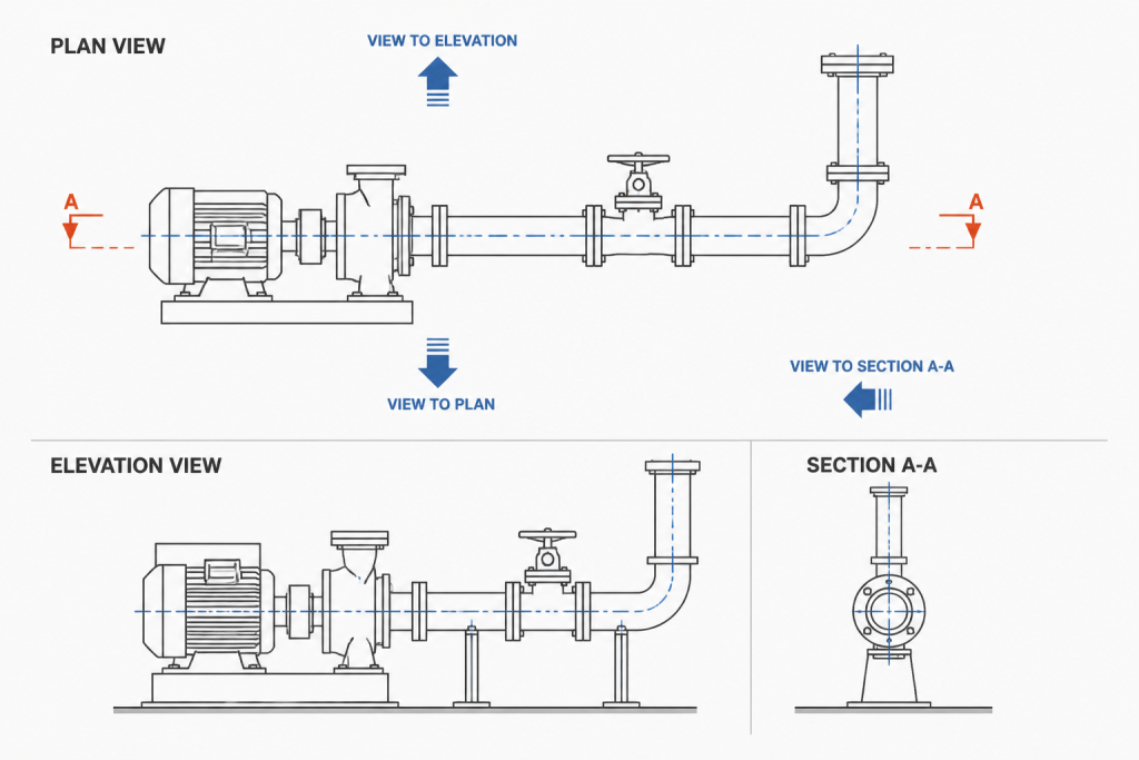
Also check whether the drawing is issued as a plan, elevation, section, or composite arrangement. A plan view looks down from above; an elevation looks from a specified horizontal direction; and a section is created by cutting through the arrangement to expose otherwise hidden relationships. The viewing direction affects how offsets, crossing lines, and equipment nozzles appear.
Read the plan view before the elevations
The plan view is usually the best starting point for understanding horizontal routing. Locate the major equipment first, then follow the main pipe corridors between them. Look for changes in direction, branches, valves, access zones, and transitions between open areas and pipe racks.
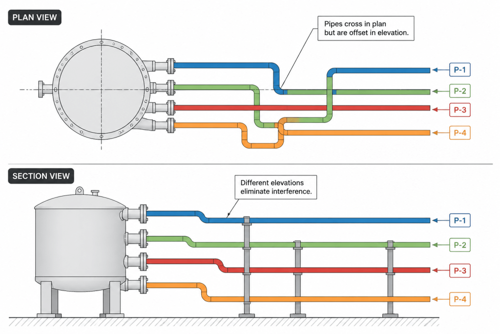
Do not interpret every crossing line as a connection. Two pipes may cross in plan while occupying different elevations. A connection should be supported by a clear junction, a branch component, a matching continuation reference, or corresponding information in another view.
When several lines share a corridor, compare their line numbers, service identifiers, and elevation callouts. A clean plan view may intentionally omit some hidden components, so the absence of a valve or fitting in plan does not prove that it is absent from the physical arrangement. Use the elevation or section view to resolve concealed geometry.
Use elevations and sections to resolve vertical relationships
Elevations explain the vertical arrangement that a plan cannot show. They help reveal which line passes above another, where a pipe rises or drops, how a branch connects to a header, and whether a valve or instrument is positioned for access.
Sections are especially useful at congested areas such as equipment nozzles, rack crossings, road crossings, platforms, and building penetrations. Trace the section line on the plan, then compare the cut view with the corresponding plan location. A section should not be read in isolation because its orientation and cutting direction determine what appears left, right, above, or below.
When an elevation appears inconsistent with a plan, check the view label and projection direction before assuming that the geometry is wrong. Many apparent errors result from reading an elevation from the wrong side or confusing a section direction arrow.
Understand the difference between graphical and dimensional information
General arrangement drawings use graphics to communicate relationships, but not every drawn distance is a controlled dimension. A line may be shown with a simplified bend, an enlarged symbol, or a schematic gap around equipment. Dimensions and coordinate callouts take priority over visual measurement.
| Drawing information | Typical purpose | Review approach |
|---|---|---|
| Centerline or route graphic | Shows the intended path and relative arrangement | Follow it between known connection points and views |
| Coordinate callout | Locates an item or point in the project reference system | Use it for model placement and cross-discipline checking |
| Elevation callout | Defines vertical location relative to the project datum | Confirm the reference level and whether it applies to centerline, support, or another point |
| Equipment or nozzle tag | Identifies the connected item and interface | Compare tag, orientation, and connection reference with equipment documentation |
| Match line or continuation note | Indicates that the arrangement continues elsewhere | Check the referenced drawing and confirm continuity |
Interpret pipe and component callouts
Callouts connect the visual layout to project data. A line number may identify service, size, material or specification grouping, insulation information, and other attributes according to the project naming system. The line number itself should not be treated as a complete design definition unless the project documentation confirms that meaning.
Component tags identify valves, instruments, specialty items, and equipment interfaces. Check that the tag is legible, located near the correct item, and consistent across related views. Leaders should terminate clearly. An ambiguous leader can associate a note with the wrong line, especially in a congested area.
Pay close attention to notes that define limits of supply, battery limits, tie-in points, temporary items, existing facilities, or future connections. These notes often control how the layout is interpreted more than the line graphic itself.
Review equipment interfaces systematically
Equipment is a fixed reference for much of the piping arrangement. For each connected nozzle or interface, verify the equipment tag, nozzle identification if provided, approximate orientation, approach direction, elevation information, and required access area.
Then ask whether the pipe route shown in the general arrangement can reach the interface without an unshown change in elevation or an uncoordinated obstruction. This is not a detailed stress or constructability analysis, but it is an effective early check for disconnected routing, incorrect nozzle sides, and misplaced equipment.
Also distinguish between a pipe terminating at a nozzle and a pipe merely passing near equipment. The visual proximity of two items is not proof of connection. Connection intent should be supported by tags, leaders, nozzle references, or matching views.
Check continuations, match lines, and drawing relationships
Large facilities are divided across multiple drawings. A continuation may be identified by a match line, arrow, coordinate reference, line number, or drawing reference. Follow every major pipe that exits the sheet and verify where it reappears.
When comparing two drawings, confirm that they use compatible orientation, revision status, coordinate basis, and area limits. A mismatch between revisions can create apparent breaks in routing or duplicate components. Record unresolved interfaces instead of silently filling them in during CAD modeling.
Common review errors
- Measuring distances from a printed drawing instead of using stated dimensions or coordinates
- Assuming that a plan-view crossing represents a physical connection
- Ignoring the viewing direction of an elevation or section
- Confusing a centerline elevation with a pipe bottom, top, or support elevation
- Reading a line number as if it were a complete specification
- Overlooking continuation references at the sheet boundary
- Using superseded drawings when checking interfaces
- Modeling ambiguous geometry without recording the underlying question
A practical review sequence
For a repeatable review, use the following order:
- Confirm the drawing identity, revision, area, orientation, and coordinate basis.
- Locate equipment, structural references, and major access zones.
- Trace primary routes in plan view.
- Use elevations and sections to resolve vertical order and hidden crossings.
- Check line numbers, component tags, leaders, and interface notes.
- Verify continuations and match lines against related drawings.
- Compare critical coordinates and elevations with the project model or source documents.
- Record unclear, conflicting, or missing information before detailed CAD development.
A well-read general arrangement drawing gives the CAD designer a reliable spatial framework without pretending to replace detailed design documents. The most valuable review habit is to separate what the drawing explicitly defines from what it merely suggests graphically. That distinction helps prevent false connections, misplaced components, and coordination problems from entering the detailed model.
How to use a piping GA drawing during design review
A general arrangement drawing is most useful when treated as a coordination document rather than an isolated picture. Compare the spatial arrangement with the relevant equipment information, piping line data, structural references, and related drawing views. Each source answers a different question, and the GA drawing helps connect those answers in physical space.
Separate confirmed interfaces from assumed geometry
During review, mark the items that are directly supported by tags, dimensions, coordinates, elevations, leaders, or referenced documents. Treat apparent connections, hidden crossings, and partially shown routes as items requiring confirmation. This approach prevents an attractive but incorrect drawing interpretation from becoming embedded in a CAD model.
Use a question-based review
- What fixed equipment or structural references control the route?
- Which view establishes the horizontal relationship, and which view resolves the vertical relationship?
- Does each line leaving the drawing have a clear continuation or interface?
- Are component tags and leaders associated with the intended pipe or equipment item?
- Are access, maintenance, and operational areas represented clearly enough for coordination?
- Which unresolved items must be returned to the responsible discipline before modeling?
Why revision control matters
A piping arrangement is dependent on its surrounding documents. A current plan compared with an outdated equipment orientation, structural layout, or continuation drawing can appear internally inconsistent even when each document was correct when issued. Confirm the document relationship before concluding that a route or interface is incorrect.
This review method is valuable for CAD drafting, model coordination, design checking, and field preparation because it records uncertainty instead of concealing it. A clear unresolved question is safer than an unverified connection or an inferred elevation.
Frequently asked questions
What is the purpose of a piping general arrangement drawing?
Its purpose is to show the physical arrangement of piping in relation to equipment, structures, access areas, and other plant systems. It communicates layout and coordination intent rather than serving as the primary fabrication document.
Should a plan-view pipe crossing be treated as a connection?
No. Pipes can cross in plan while occupying different elevations. Confirm a connection through a junction, branch component, matching reference, equipment interface, or supporting information in another view.
Why are elevations and sections important?
They reveal vertical order, rises and drops, branch relationships, concealed routing, and access conditions that may not be clear in plan view. Always check the view direction and section orientation.
Can distances be measured directly from a printed GA drawing?
Visual measurement should not replace stated dimensions, coordinates, or elevation callouts. Drawn graphics may be simplified or enlarged to improve readability.
What should be done when a pipe stops at the sheet boundary?
Check for a match line, continuation note, coordinate reference, line reference, or related drawing. The sheet edge does not by itself establish the physical termination of the pipe.
How does a GA drawing support CAD development?
It provides a spatial framework for placing equipment, routing piping, coordinating structures, and identifying interfaces. Ambiguous or missing information should be recorded and resolved before detailed geometry is finalized.