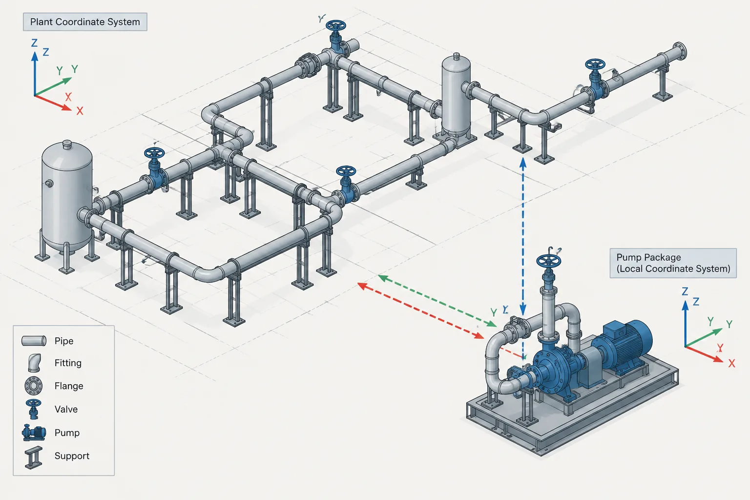
Plant coordinates vs. local coordinates in piping CAD is primarily a question of reference control. Plant coordinates place objects within the wider facility, while local coordinates describe geometry from a convenient equipment, package, spool, or model datum. Both can represent the same physical item correctly, but only when the origin, axis orientation, elevation datum, and transformation between them are known.
This reference explains how coordinate frames affect model placement, equipment nozzles, drawing interpretation, multidisciplinary exchange, and field comparison. It also outlines practical checks for detecting geometry that has been translated, rotated, mirrored, or vertically misplaced during model coordination.
Piping CAD coordinate systems determine where every pipe, support, nozzle, and equipment item exists in relation to the facility. When those systems are controlled correctly, designers can exchange models, connect piping across unit boundaries, generate consistent drawings, and compare design coordinates with field survey data. When they are misunderstood, geometry may appear correct within one model but arrive shifted, rotated, or at the wrong elevation in another.
The main difficulty is that a project may use several coordinate frames at the same time. A plant grid can locate facilities across the site, an area model may use a convenient working origin, and an equipment model may describe nozzle locations from a local datum. These coordinate systems are not competing descriptions. They are different frames of reference that must be connected by documented transformations.
What Is a Coordinate System in Piping CAD?
A coordinate system defines an origin, axis directions, and a method for expressing position. A piping component’s location is meaningful only when the coordinate frame is known. The same coordinate values can describe entirely different physical locations if they are interpreted from different origins or axis orientations.
Most plant design work expresses horizontal position using directions such as east and north, with a separate elevation value. CAD software may internally label the axes differently. The project must therefore define how the software axes correspond to the project’s physical directions.
A complete coordinate definition should establish:
- The location of the origin.
- The positive direction of each horizontal axis.
- The vertical datum and positive elevation direction.
- The relationship between plant north, true north, and drawing north where applicable.
- Any translation or rotation applied to referenced models.
- The units and coordinate precision used for exchange.
Common Coordinate Frames on a Piping Project
| Coordinate frame | Typical purpose | Main control concern |
|---|---|---|
| Site or plant coordinates | Locating facilities, structures, roads, underground systems, and survey points across the project | Consistency with the approved site and survey grid |
| Area coordinates | Organizing a process unit or model work area | Documented relationship to the plant coordinate system |
| Equipment-local coordinates | Defining nozzles, supports, internals, or vendor geometry relative to the equipment | Correct equipment origin, orientation, and installed elevation |
| Drawing coordinates | Placing views, annotations, and details on a sheet | Avoiding confusion between paper-space location and physical model location |
| Fabrication-local coordinates | Describing a spool, skid, or module from a convenient fabrication datum | Clear mapping to installed plant position |
Terminology varies between companies and software environments. One project may call the controlling frame the plant grid, while another uses site coordinates or global coordinates. The name matters less than the documented definition and consistent application.
Global Does Not Always Mean Survey Control
In CAD discussions, global often means the highest-level coordinate system within a model or software session. It does not automatically mean that the coordinates match a licensed survey grid, geographic coordinate system, or civil design surface.
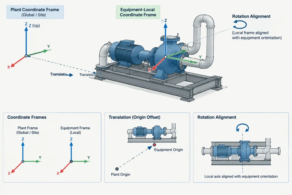
This distinction is important when piping models are exchanged with civil, structural, architectural, or geospatial teams. A model can be internally consistent and still require a translation or rotation before it aligns with the official site control. Designers should not assume that a file labeled global is ready for direct field staking or survey comparison.
Why Local Coordinate Systems Are Useful
Large plant coordinates can be inconvenient for detailed equipment and skid design. A vendor may define the baseplate corner, vessel centerline, pump shaft, or package datum as a local origin. Nozzle positions can then be communicated relative to a recognizable physical reference.
Local coordinates also simplify repeated assemblies. A standard package can be designed around its own origin and later placed at the required plant location. The placement operation adds the translation and rotation needed to relate package geometry to the site.
The risk is not the use of local coordinates. The risk is losing the transformation between the local and plant frames. A package model without a defined insertion point, orientation reference, and installed elevation can be difficult to position reliably.
Translation, Rotation, and Elevation
A coordinate transformation may contain several independent elements:
- Translation: moving the local origin to its plant location.
- Rotation: aligning local equipment or package axes with the plant axes.
- Vertical placement: setting the local datum at the correct project elevation.
- Axis mapping: reconciling differences in how software applications identify horizontal and vertical axes.
Mirroring should be treated with particular caution. A mirrored piping assembly is not always equivalent to a rotated assembly. Valve handwheels, eccentric reducers, branch orientations, drain points, instrument connections, and equipment handedness may change. If a package requires an opposite-hand arrangement, it should be checked as a distinct configuration rather than assumed to be a harmless coordinate transformation.
Coordinate Control at Equipment Nozzles
Equipment nozzles are common interface points between local and plant coordinates. Vendor information may locate a nozzle by its elevation, radial or planar position, projection, and orientation relative to an equipment datum. The plant model must then place that equipment datum correctly before the piping connection can be trusted.
A sound interface check separates two questions:
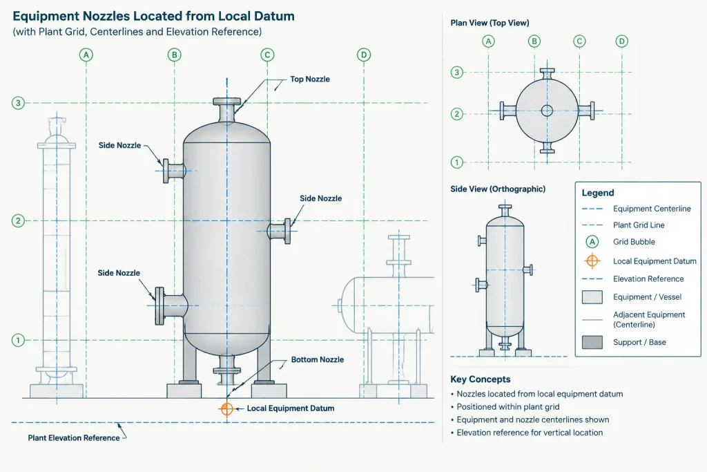
- Is the nozzle correct relative to the equipment’s local reference?
- Is the equipment correctly located and oriented in the plant model?
Checking only the first question can leave every nozzle consistently wrong in plant space. Checking only the second can hide an incorrect nozzle definition within an otherwise correctly positioned equipment model.
Coordinates on Plans, Isometrics, and Fabrication Drawings
Different drawing types use coordinates for different purposes. A piping plan may show grid lines and key centerline locations. An isometric may report connection-point coordinates or elevations while relying on dimensions to define the spool geometry. A fabrication drawing may use a local spool datum because the fabricator does not need the full plant grid for every cut and weld.
These approaches can coexist, but the drawing should make the reference frame clear. A coordinate label without a stated datum can create false confidence. The reader may assume it is a plant coordinate when it is actually relative to a package or drawing origin.
Coordinates should also not be used as a substitute for sensible dimensioning. A collection of rounded coordinate labels may not adequately control fitting takeouts, face locations, or cut lengths. Coordinates locate geometry in a reference frame; fabrication dimensions define the required physical relationships.
Model Referencing and Data Exchange
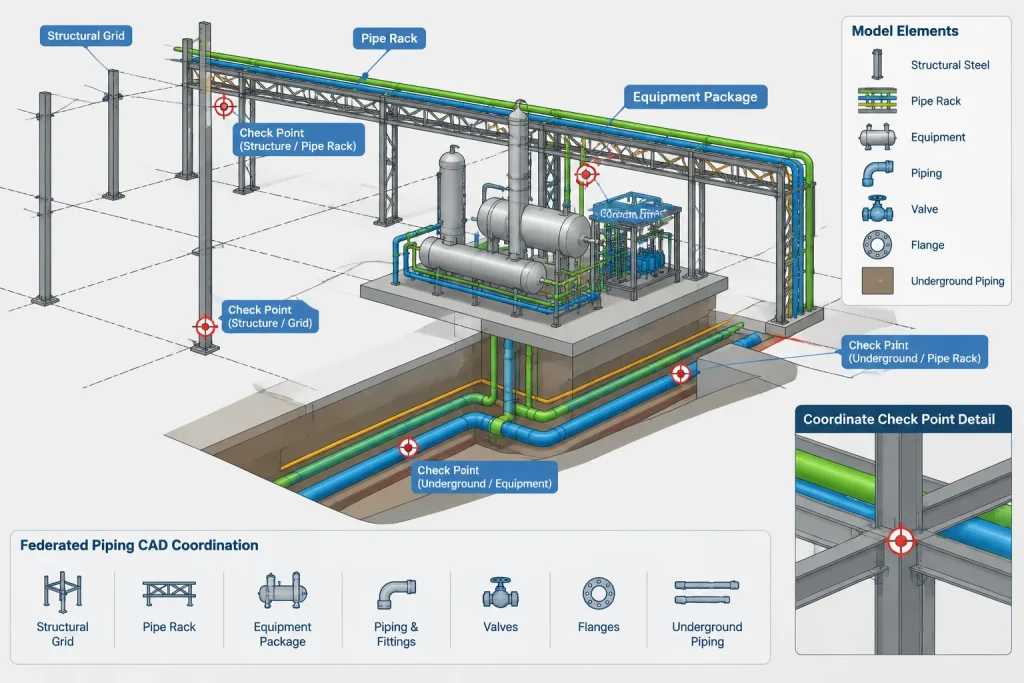
Federated plant models often combine files from multiple disciplines. Some files remain in plant coordinates, while others are attached as references using saved transformations. Either method can work if the project has a controlled convention.
Before exchanging a piping model, confirm:
- Whether the recipient expects plant-space or local-space geometry.
- Which origin and axis directions are used.
- Whether a reference transform has already been applied.
- Whether elevations use the same project datum.
- Whether units will be interpreted correctly by the receiving application.
- Whether equipment and piping identifiers remain attached after export.
A frequent failure occurs when geometry is exported in plant coordinates and then attached using the same transformation that was used in the source model. The offset is applied twice. The opposite problem occurs when local geometry is imported without its required transform and appears near the software origin.
Practical Coordinate Verification Workflow
Establish controlled check points
Select recognizable locations that can be verified across disciplines, such as structural grid intersections, equipment centerlines, column lines, or designated survey-control points. Check points should be distributed through the area rather than concentrated near one origin.
Compare position and orientation
A single matching point confirms translation but may not reveal rotation. Compare additional points along different directions. Also verify a known elevation so that horizontal agreement does not conceal a vertical datum error.
Test interface geometry
Inspect piping tie-ins, equipment nozzles, rack boundaries, underground transitions, and package battery limits. These interfaces expose coordinate errors quickly because independently produced models must meet at the same physical location.
Record the transformation
Do not rely on an operator remembering how a reference was moved. Record the source coordinate frame, destination frame, translation, rotation convention, elevation treatment, units, file revision, and responsible party in the project’s model-control process.
Recheck after updates
A replaced reference file may arrive in a different coordinate state even when its filename remains similar. Verify control points after significant model updates instead of assuming that a previous attachment transform is still valid.
Common Coordinate-Control Errors
- Confusing drawing north with plant north.
- Using the wrong sign for an east, north, or elevation offset.
- Applying a reference translation twice.
- Rotating about the software origin instead of the intended package datum.
- Mixing topographic elevation with a project-local elevation datum.
- Importing geometry with incorrect units.
- Moving referenced geometry manually without recording the change.
- Publishing coordinates rounded beyond the precision needed for the intended task.
- Treating an equipment-local nozzle coordinate as a plant coordinate.
A Coordinate-Control Checklist for Piping CAD
- Identify the controlling plant or site coordinate system.
- Define the relationship between software axes and physical directions.
- Confirm the project elevation datum.
- Document each local model origin and orientation reference.
- Use multiple check points to verify translation, rotation, and elevation.
- Confirm coordinate state before exporting or attaching a model.
- Keep model transformations under revision control.
- Verify critical interfaces after reference updates.
- Do not use CAD coordinates directly for construction or survey work without project-required review and verification.
Coordinate Systems Are Part of Design Data
A piping model’s coordinate frame is not merely a software setting. It is controlled design information that affects multidisciplinary coordination, fabrication interfaces, field verification, and drawing interpretation. Good coordinate management makes local equipment data usable in the larger plant context while preserving convenient modeling workflows.
The most reliable approach is to define each coordinate frame explicitly, preserve the transformation between frames, and verify the result using known points and physical interfaces. That process prevents a model that is geometrically correct in isolation from becoming incorrectly located when it enters the full project environment.
How to Diagnose a Coordinate Mismatch
When referenced piping does not align, begin by identifying the coordinate state of each file rather than moving geometry until it appears correct. Determine whether the source was exported in plant space or local space, whether the receiving model applies a saved transformation, and whether both files use the same elevation datum and axis mapping.
The visual pattern of the mismatch can help direct the review:
- Uniform displacement: investigate the origin, translation, units, and whether an offset was omitted or applied more than once.
- Alignment near one point but increasing separation elsewhere: investigate rotation, axis direction, and the point about which the model was rotated.
- Correct plan location but incorrect height: investigate elevation datum, vertical-axis mapping, and equipment installation level.
- Correct equipment position but incorrect nozzle connections: investigate the equipment-local nozzle definition and equipment orientation separately.
- Opposite-hand geometry: investigate mirroring and component handedness rather than treating the issue as an ordinary rotation.
Coordinate Information to Preserve With a Model
A model handoff is more reliable when its coordinate definition travels with the geometry. The accompanying model-control information should identify the source frame, destination frame, local datum, plant placement, rotation convention, elevation treatment, units, revision status, and approved control points. It should also state whether the delivered file already contains the placement transformation.
This information helps reviewers distinguish an intentional local model from an incorrectly located plant model. It also reduces the chance that a receiving team will repeat a transformation, remove one that is still required, or interpret drawing-space coordinates as physical plant locations.
Drawing and Model Review Principle
Coordinates should be reviewed as controlled design data, not merely as labels displayed by CAD software. Before accepting a model or drawing, verify that the stated coordinate frame agrees with recognizable physical references and with the intended use of the deliverable. Construction, survey, fabrication, and installation activities should follow the project’s required review and verification procedures rather than relying on unconfirmed screen coordinates.
Frequently Asked Questions
Are plant coordinates and global coordinates always the same?
No. Global may describe the highest-level frame inside a CAD application or model session. It does not necessarily mean the file matches the approved plant grid, civil control, or survey reference.
Can a local-coordinate model be used in a federated plant model?
Yes, provided its insertion point, axis orientation, elevation datum, units, and transformation to plant coordinates are documented and applied consistently.
Why is one matching control point not enough?
A matching point can confirm that a translation reaches that location, but it may not expose an incorrect rotation or axis direction. Distributed points and a known elevation provide a more complete check.
Should misaligned referenced geometry be moved manually?
Not without identifying and recording the cause. An undocumented manual move can hide an export, origin, rotation, or datum problem and may be lost or duplicated when the reference is updated.
Can coordinates replace piping dimensions?
No. Coordinates locate objects within a reference frame, while dimensions control physical relationships such as fitting placement, face locations, and fabrication geometry. Drawings may require both.
Why can every nozzle be wrong even when the vendor model is internally consistent?
The nozzle locations may be correct relative to the equipment-local datum while the equipment itself is incorrectly translated, rotated, or elevated in plant space. Both the local nozzle definition and the plant placement must be checked.