
Pipe roughness in flow calculations is a controlled hydraulic assumption, not a property that can be inferred reliably from nominal size, material name, or CAD geometry alone. The selected value must correspond to the actual wetted surface, pipe condition, bore basis, units, and calculation method.
This guide explains the distinction between absolute and relative roughness, shows why inside diameter and surface condition must be evaluated together, and outlines how roughness data can be transferred between piping models, line records, and hydraulic calculations without becoming an uncontrolled default.
Pipe roughness is a hydraulic input used to estimate friction losses in a flowing system. It describes the texture of the pipe’s internal surface, but it is not simply a material label or a dimension that can be read from a generic CAD model. Manufacturing method, lining, coating, corrosion, deposits, and service history can all affect the condition seen by the fluid.
This distinction matters because a geometrically correct piping model may still be incomplete for hydraulic analysis. A model can identify nominal pipe size, schedule, material, and route length without establishing the roughness value appropriate for the calculation. Designers should therefore treat roughness as controlled engineering data rather than an automatic property of a pipe cylinder.
What Does Pipe Roughness Mean?
In hydraulic calculations, roughness represents small irregularities on the wetted internal surface of a pipe. These irregularities interact with the fluid near the wall and can influence resistance to flow.
The engineering value assigned to roughness is normally an equivalent parameter used by a selected calculation method. It should not be interpreted as a complete microscopic description of the surface. Two pipes that appear different under close inspection may be represented by the same design assumption, while two pipes of the same nominal material may require different assumptions because of lining or operating condition.
Roughness should also be kept separate from several related concepts:
- Wall thickness controls the difference between outside diameter and inside diameter.
- Corrosion allowance is a design addition to required wall thickness, not a roughness value.
- Dimensional tolerance describes permitted variation in manufactured geometry.
- Ovality describes departure from a circular cross-section.
- Surface finish may be specified or measured in several ways and is not automatically interchangeable with hydraulic roughness.
Absolute Roughness and Relative Roughness
Absolute roughness
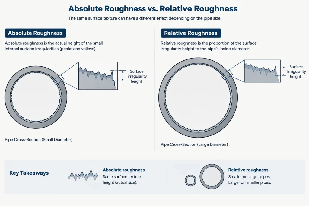
Absolute roughness is expressed as a length. It represents the effective height of internal surface irregularities for the purpose of a hydraulic model. The assumed value must use units consistent with the rest of the calculation.
A value should come from an approved project basis, calculation procedure, reliable technical reference, test data, or verified manufacturer information. It should not be copied from an unrelated material description without checking pipe condition and calculation context.
Relative roughness
Relative roughness compares absolute roughness with the pipe’s internal diameter. It is dimensionless and is commonly represented conceptually as:
Relative roughness = absolute roughness / internal diameter
This relationship explains why the same absolute roughness does not have the same significance in every pipe size. A given surface irregularity occupies a larger proportion of a small bore than of a large bore.
The diameter used in this ratio must represent the hydraulic passage being analyzed. Nominal pipe size is a designation, not the actual inside diameter. Where schedule, lining, corrosion, or deposits change the bore, the hydraulic diameter input must be reviewed accordingly.
How Roughness Affects Pressure-Loss Calculations
In calculations based on the Darcy-Weisbach approach, pressure loss depends on factors that include pipe length, internal diameter, fluid velocity, density, and friction factor. The friction factor is determined from the applicable flow regime and calculation method, with Reynolds number and relative roughness being important inputs for turbulent flow.

In idealized fully developed laminar flow, wall roughness is generally not used in the same way as it is for turbulent flow. This is one reason a roughness value should not be treated as a stand-alone answer. The engineer must also know the fluid properties, flow rate, temperature basis, and selected hydraulic method.
Some industries use empirical formulas with their own condition or resistance coefficients. For example, a coefficient used in one empirical water-flow method is not the same quantity as absolute roughness used with a Darcy-based method. The values should not be substituted for one another merely because both account for pipe condition.
Why Material Alone Is Not Enough
Material is useful when selecting an initial assumption, but it does not completely define the wetted surface. The following conditions can change the appropriate hydraulic basis:
- Seamless, welded, drawn, cast, or otherwise manufactured product forms
- Internal coatings or cementitious, polymeric, metallic, or other linings
- Joint offsets, weld penetration, backing material, or internal transitions
- Corrosion, erosion, scaling, fouling, or biological growth
- Cleaning, pigging, chemical treatment, or rehabilitation history
- Degradation, blistering, cracking, or partial loss of a lining
- Service fluid, temperature, solids content, and operating duration
A new lined pipe and an older unlined pipe may share the same nominal size and base material while presenting very different hydraulic surfaces. Conversely, a conservative project assumption may intentionally group several similar materials under one documented design value.
Pipe ID, Deposits, and the Double Effect of Aging
Aging can influence a hydraulic model in more than one way. Internal deposits may increase effective roughness while also reducing the available bore. These effects should not be collapsed into a single undocumented adjustment.
Reduced diameter increases velocity for a fixed volumetric flow rate, and diameter itself has a strong influence on friction loss. Increased roughness can additionally affect the friction factor. Using the original pipe ID with a roughness value for an aged pipe may therefore miss part of the expected restriction.

For existing systems, field measurements, inspection records, cleaning history, operating data, and engineering judgment may be more relevant than a generic new-pipe reference. The basis should state whether the model represents clean, normal operating, aged, fouled, or another defined condition.
What CAD and Piping Databases Should Store
A CAD component library usually needs geometric and specification data, but hydraulic assumptions may belong in a separate engineering dataset. The correct structure depends on how the organization connects design models, line lists, process simulations, and calculation tools.
| Data item | Typical role | Control concern |
|---|---|---|
| Nominal pipe size | Component designation and connectivity | Do not use it as actual bore |
| Schedule or specified wall | Determination of nominal geometry | Confirm the applicable dimensional source |
| Calculated or selected ID | Flow area and relative roughness | Account for lining or deposits where required |
| Base material | Specification and material control | Material name alone does not define roughness |
| Internal lining or coating | Wetted-surface identification | Record type and condition basis separately |
| Absolute roughness | Hydraulic calculation input | Include units, source, and condition basis |
| Design condition | Defines clean, aged, fouled, or other state | Avoid ambiguous default values |
| Calculation method | Identifies how the input is used | Do not mix unrelated coefficient systems |
If roughness is stored as a property, the record should include units and metadata. A bare number is unsafe because users may not know whether it represents absolute roughness, relative roughness, an empirical coefficient, or a value expressed in another unit system.
A Practical Data-Transfer Workflow
- Confirm the line identity. Match the hydraulic segment to the correct line number, service, and operating case.
- Determine the bore basis. Use verified pipe dimensions and include internal lining or expected deposit thickness when the calculation basis requires it.
- Define the wetted surface. Identify the surface actually contacting the fluid rather than relying only on the base pipe material.
- Select the condition case. State whether the model represents new, clean, aged, fouled, maximum restriction, or another project-defined condition.
- Apply the approved roughness source. Record the value, units, calculation method, and basis of selection.
- Check transitions. Review reducers, valves, fittings, liners, hoses, and equipment passages that may have different bores or resistance treatments.
- Preserve traceability. Keep assumptions linked to the calculation revision rather than burying them in an informal CAD note.
Common Modeling and Review Errors
- Using NPS or DN as though it were the exact internal diameter
- Assigning one roughness value to every pipe made from the same base material
- Ignoring a lining that defines the actual wetted surface
- Accounting for fouling through roughness but not through reduced bore
- Mixing absolute roughness with an empirical flow coefficient
- Transferring a value without transferring its units
- Using a new-pipe assumption for an existing system without documenting the decision
- Embedding hydraulic data in a generic CAD block and allowing it to become an uncontrolled default
Key Takeaway
Pipe roughness is not visible in ordinary routing geometry, and it cannot be established from nominal size or material name alone. Reliable flow calculations require a coordinated basis covering actual internal diameter, wetted-surface condition, roughness definition, units, and calculation method.
CAD should provide accurate routing, lengths, sizes, specifications, and component relationships. Hydraulic analysis should add controlled assumptions about fluid behavior and internal condition. Keeping those roles connected—but not confused—produces calculations that are easier to review, revise, and defend.
How to Review a Roughness Assumption
A useful review separates physical geometry from hydraulic condition. Geometry establishes the flow passage, while the condition basis describes the surface encountered by the fluid. Both can change independently and both can affect the calculated result.
Geometry questions
- Was the actual inside diameter derived from the applicable pipe dimensions rather than from the nominal designation?
- Does the bore account for an internal lining, coating, deposit, or other restriction required by the design case?
- Are transitions and components with different internal passages represented appropriately?
Condition questions
- Does the roughness assumption describe the wetted surface rather than only the base pipe material?
- Is the condition identified as clean, aged, fouled, rehabilitated, or another project-defined case?
- Are the source, units, calculation method, and reason for selecting the assumption recorded?
Data-control questions
- Can reviewers distinguish absolute roughness from relative roughness and from coefficients used by other flow methods?
- Is the hydraulic input tied to a calculation revision or approved engineering dataset?
- Will a change to lining, service condition, or expected deposits trigger a review of both roughness and bore?
This separation makes revisions easier to audit. A routing change may alter length without changing surface condition, while a lining change may alter both the wetted surface and effective inside diameter even when the nominal pipe designation remains unchanged.
CAD Geometry Versus Hydraulic Data
A CAD model can support hydraulic analysis by supplying verified routing lengths, component relationships, pipe specifications, and dimensional references. It does not automatically establish the internal condition assumed by a flow calculation.
Where roughness is connected to a model or piping database, it should be treated as attributed engineering data with clear ownership. The record should identify what the value represents, which units apply, what condition it describes, and which calculation method consumes it. This prevents a convenient library property from being reused outside its intended context.
Frequently Asked Questions
Is pipe roughness the same as surface finish?
No. Surface finish may be described or measured using methods that do not directly provide the equivalent roughness required by a hydraulic model. Any conversion or relationship must be supported by the approved calculation basis rather than assumed from terminology alone.
Can roughness be selected from pipe material alone?
Material can help identify a starting reference, but it does not fully define the wetted surface. Manufacturing method, lining, coating, corrosion, deposits, cleaning history, and service condition may all affect the appropriate assumption.
Why is nominal pipe size unsuitable for relative roughness?
Nominal pipe size is a designation rather than the actual hydraulic bore. Relative roughness requires an internal diameter that represents the flow passage used in the analysis.
Should fouling be represented only by a higher roughness?
Not necessarily. Fouling or deposits may change the surface condition and reduce the available bore. Treating only roughness while leaving the original inside diameter unchanged can omit an important part of the restriction.
Can a roughness value be embedded in a CAD component?
It can be stored as attributed data, but it should not become an undocumented universal default. Its definition, units, source, condition basis, calculation method, and revision control should remain visible to calculation users.
Is absolute roughness interchangeable with an empirical flow coefficient?
No. Different hydraulic methods use different inputs and coefficient systems. Values should only be used with the method for which they were selected or established.
Who should approve the roughness basis?
Approval should follow the project’s engineering and calculation-control procedure. CAD users may transfer the data, but the hydraulic assumption should remain traceable to an authorized technical basis.