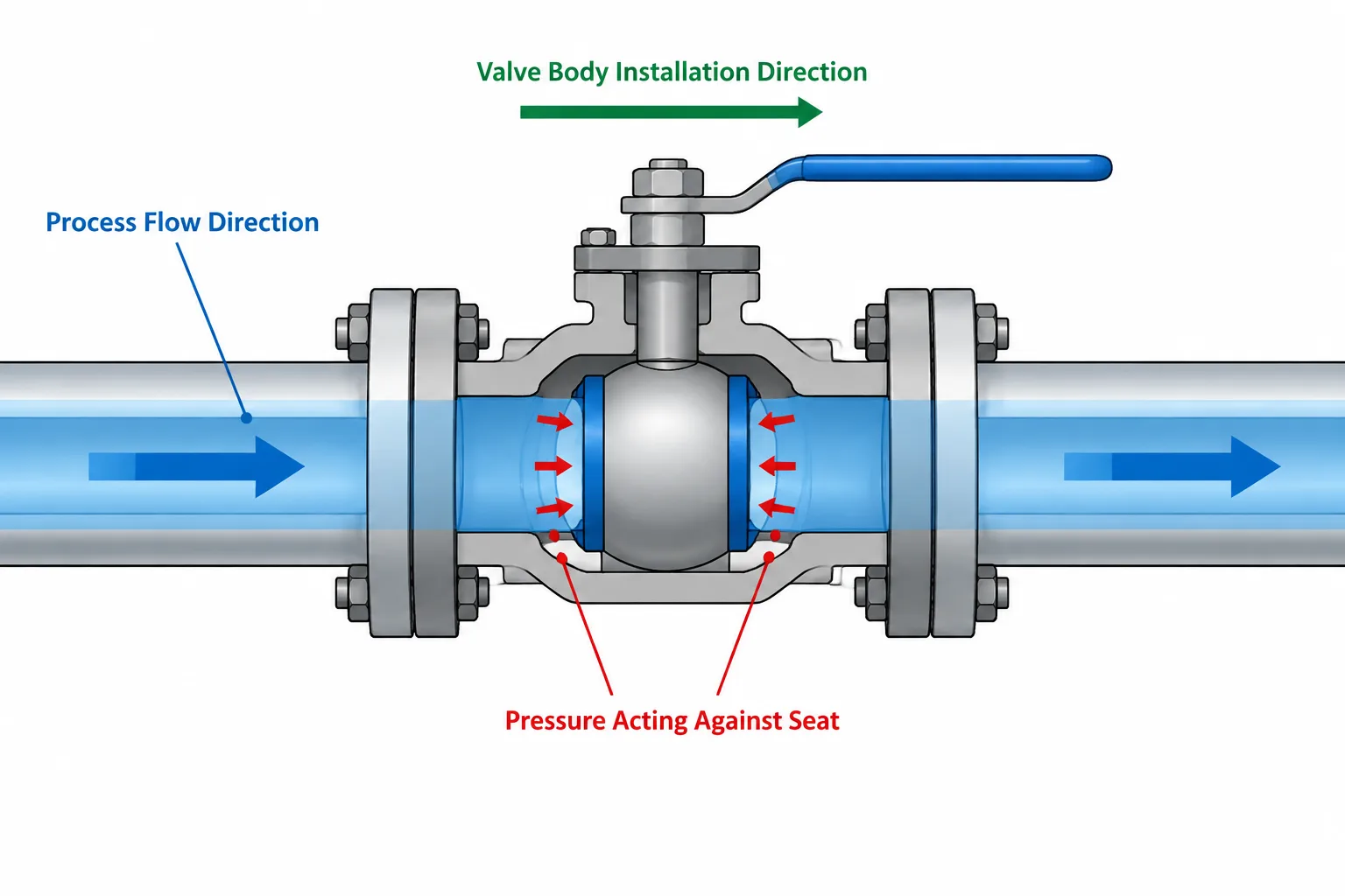
Directional vs. bidirectional valves must be evaluated by function, not by the apparent symmetry of a piping symbol or model. A valve body that connects neatly in either orientation may still have a defined upstream side, preferred flow direction, or pressure side for effective shutoff.
This guide explains how to keep process flow, sealing direction, body orientation, and operator arrangement separate during P&ID review, piping modeling, and drawing production. It also provides a practical basis for checking valve data before fabrication, installation, or replacement.
A valve shown on a P&ID may look symmetrical, and its 3D CAD model may fit between the same two pipe connections in either orientation. That does not mean the actual valve can be installed either way. Internal geometry, seat design, actuator arrangement, pressure-assist behavior, and manufacturer instructions may establish a required or preferred flow direction.
Understanding directional vs. bidirectional valves is therefore more than a symbol-reading exercise. Designers must distinguish process flow, permitted reverse flow, shutoff performance, and physical installation orientation. These concepts affect P&IDs, piping layouts, valve data, procurement, construction, and future replacement work.
What Does Directional Mean for a Valve?
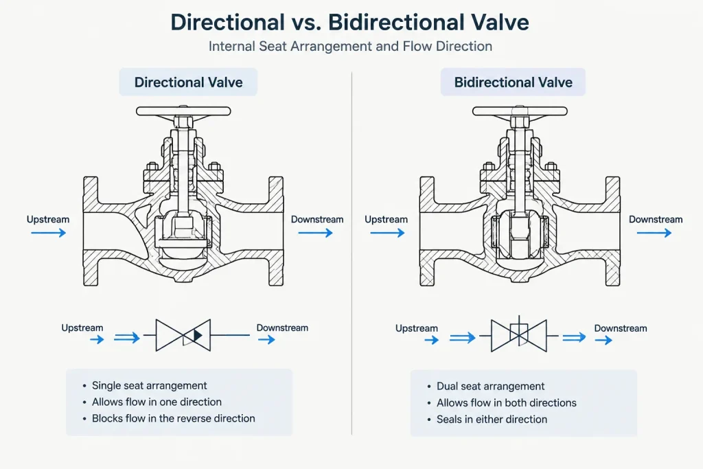
A directional valve is designed or specified to operate with flow, pressure, or both applied in a particular direction. Its body may carry a cast, stamped, engraved, or attached arrow identifying that direction. The required orientation may be related to normal operation, pressure drop, seat loading, closure behavior, or protection of internal parts.
A bidirectional valve can accommodate flow from either connected side within the limits of its particular design and service. However, the word bidirectional should not automatically be interpreted as identical performance in every condition. A valve may pass flow in both directions while providing its best shutoff performance against pressure from only one side.
Directionality should therefore be evaluated as several separate questions:
- Can process fluid flow through the valve in either direction?
- Can the valve close reliably against pressure from either side?
- Is tight shutoff expected in one direction or both directions?
- Does the manufacturer identify a preferred installation direction?
- Does the application require isolation of pressure from a specific side?
Flow Direction Is Not the Same as Sealing Direction
Process flow direction describes the expected movement of fluid through the line during a defined operating case. Sealing direction describes the side from which pressure acts when the closed valve is expected to isolate the system. Those directions are often related, but they are not interchangeable.
For example, a line may normally flow from upstream equipment toward downstream equipment. During shutdown, testing, cleaning, or an abnormal operating case, pressure may be applied from the opposite side. A valve selected only around normal flow could perform differently when asked to isolate that reverse pressure.
This distinction is especially important where a closed valve establishes an equipment boundary, maintenance boundary, pressure-test boundary, or separation between systems. The piping designer should not determine acceptable isolation performance from the appearance of a generic CAD model.
| Term | Practical meaning | CAD or documentation concern |
|---|---|---|
| Normal flow direction | Expected process flow during the stated operating condition | Usually communicated on the P&ID and related process documents |
| Required installation direction | Orientation necessary for the selected valve to function as intended | May require an arrow, note, keyed model orientation, or installation detail |
| Preferred flow direction | Recommended direction even if limited reverse operation is possible | Must remain visible to reviewers and installers |
| Sealing direction | Side from which pressure acts when shutoff performance is required | Should be verified against the valve design and isolation philosophy |
| Reverse-flow case | An operating, testing, or transient case opposite normal flow | May not be apparent from a single flow arrow |
Valve Type Alone Does Not Prove Directionality
Some valve functions strongly indicate directional behavior. A check valve is intended to permit flow in one direction and resist reverse flow. Many control-valve arrangements also depend on a defined relationship between upstream pressure, downstream pressure, trim, and actuator action.
Other valve categories require more caution. Gate, globe, ball, plug, and butterfly valves are broad families containing many internal designs. Two valves with the same general type and end connections may have different seating arrangements or installation recommendations. Features such as a single seat, resilient seat, offset disc, cavity-relief arrangement, or pressure-assisted seal can influence directionality.
Consequently, rules such as “all ball valves are bidirectional” or “the handwheel side identifies upstream” are unreliable. Directionality should be established from approved project data and manufacturer information for the actual valve being supplied.
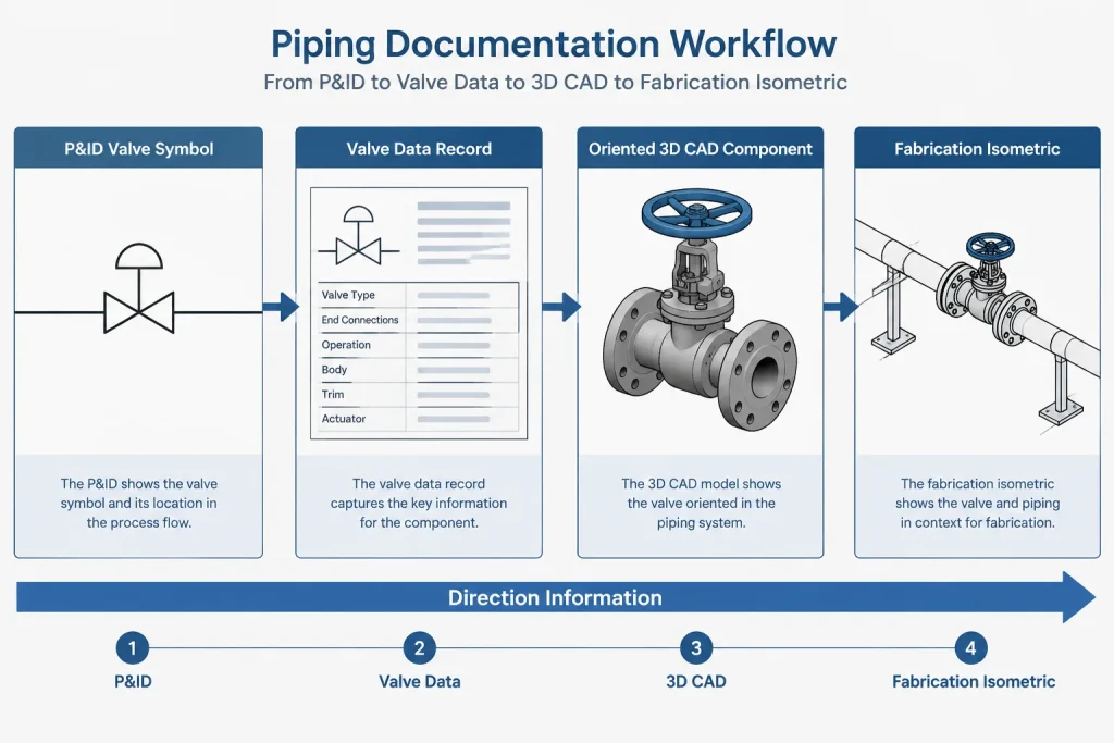
How Direction Is Communicated Across Project Documents
P&IDs
A P&ID communicates process intent rather than complete installation geometry. Line arrows generally show process flow, but they do not necessarily prove that every valve on the line has a mandatory body orientation. A directional valve symbol, note, tag attribute, or associated specification may provide additional information.
The P&ID should also be read in the context of alternate operating modes. Startup, shutdown, bypass operation, regeneration, backflow, and testing may create conditions not represented by the main arrow alone.
Valve data and project specifications
Valve data sheets, material classes, requisitions, and approved vendor documents may define seat construction, flow direction, shutoff expectations, and installation requirements. These records are more authoritative for the purchased component than assumptions based on a generic library symbol.
3D piping models
A 3D model can show the physical orientation of a valve body, operator, and connected piping. It may also contain port directions or flow attributes. However, visible symmetry can hide functional asymmetry. If direction matters, the component should be inserted with a consistent upstream-to-downstream convention and carry reviewable direction data.
Isometrics and installation drawings
Fabrication and installation documents must give the field enough information to orient the valve correctly. Depending on project practice, this may include a flow arrow, orientation note, tagged directional symbol, or reference to approved valve documentation. An arrow should be placed so that it cannot be mistaken for a dimension leader, slope indicator, or continuation symbol.
A Practical CAD Workflow for Directional Valves
- Establish the operating direction. Read the P&ID, line list, and process information. Identify whether flow can reverse under any credible operating or test condition.
- Identify the required valve function. Determine whether the valve is used for throttling, non-return service, isolation, emergency action, or another function. Avoid assigning direction solely from its graphical symbol.
- Verify the selected component. Review the approved valve data and manufacturer documentation. Confirm required flow orientation, sealing direction, and any limitations on reverse pressure.
- Orient the model component. Align the model ports and directional attribute with the established upstream and downstream connections. Do not mirror a directional component without checking what happens to its flow metadata.
- Coordinate the operator. Flow orientation and operator orientation are different controls. After setting the body direction, check handwheel, lever, gearbox, actuator, tubing, and maintenance access.
- Transfer the information to deliverables. Ensure that direction remains understandable on isometrics, plans, sections, valve schedules, and installation documents.
- Review replacements independently. A replacement valve with matching end-to-end dimensions may still have a different seating direction or installation requirement.
Common CAD and Review Errors
- Using the line arrow as the only installation instruction: The line arrow shows process intent but may not define valve-specific orientation.
- Assuming a symmetrical body is bidirectional: Internal seats and trim may not be symmetrical even when the exterior is.
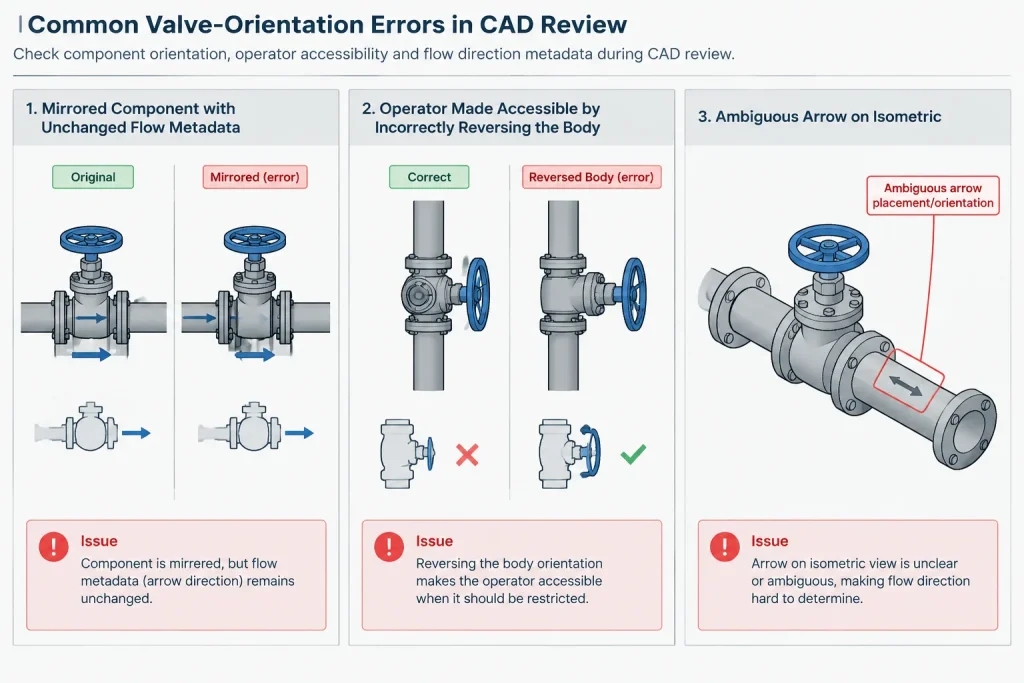
- Rotating the operator by reversing the entire valve: Turning the valve end for end is not a safe substitute for changing an operator arrangement.
- Mirroring a block without updating attributes: The graphics may reverse while stored port names or flow data remain unchanged.
- Ignoring temporary reverse pressure: Hydrostatic testing, flushing, cleaning, or another operating mode can load the seat from the opposite side.
- Replacing a valve by envelope alone: Matching connection size, end type, and overall length does not establish functional interchangeability.
- Adding arrows without a defined meaning: Drawings should make clear whether an arrow represents process flow, mandatory installation direction, or another condition.
Directionality Review Checklist
- Is normal process flow clearly identified?
- Are reverse-flow or reverse-pressure cases known?
- Has the actual valve design been checked rather than inferred from valve type?
- Is the required sealing direction documented?
- Does the 3D component have a consistent upstream and downstream orientation?
- Are body direction and operator accessibility checked separately?
- Do isometric arrows and notes agree with the P&ID and approved valve data?
- Could mirroring, copying, or substitution have reversed the intended orientation?
- Can a fabricator or installer understand the requirement without guessing?
Key Takeaway
Directional vs. bidirectional valve behavior cannot be established from exterior shape or generic valve type alone. Process flow, installation direction, and sealing direction are related but distinct pieces of information. Good piping documentation keeps those concepts separate, verifies them against the selected valve, and communicates any required orientation from the P&ID through the 3D model and installation drawing.
The safest CAD practice is to treat valve direction as controlled engineering data rather than an incidental graphical property. That approach reduces reversed installations, misleading model substitutions, and isolation assumptions that the supplied valve may not support.
Treat Direction as Controlled Valve Data
Direction should remain traceable as valve information moves between process documents, specifications, the piping model, isometrics, and field deliverables. A graphical arrow is useful only when its meaning is defined and it agrees with the approved information for the selected valve.
Separate graphics from component attributes
A CAD symbol can indicate process intent, while component properties can record the modeled upstream and downstream ports. Keeping these functions distinct helps reviewers identify cases where a block was mirrored, a component was swapped, or the visible arrow no longer agrees with its stored orientation.
Preserve direction through model changes
Directionality deserves another check whenever a valve is copied, replaced, mirrored, or turned to resolve an operator-access problem. The body should not be reversed merely to reposition a lever, handwheel, gearbox, or actuator. Operator arrangement and valve flow orientation are separate design decisions.
Make the installation requirement unambiguous
Installation drawings should distinguish a valve-specific orientation marker from ordinary process-flow arrows and other drawing symbols. Where the requirement cannot be communicated clearly by graphics alone, a concise note or reference to the approved valve documentation can prevent interpretation in the field.
Recommended Review Handoff
- Process review: Confirm normal flow and any credible reverse-flow or reverse-pressure condition.
- Valve review: Confirm the required installation and sealing direction from approved component information.
- Model review: Check port orientation, directional attributes, body position, and operator access independently.
- Drawing review: Verify that P&IDs, layouts, isometrics, schedules, and notes communicate a consistent requirement.
- Change review: Recheck direction whenever the specified valve or modeled component is substituted.
This information chain is especially important because dimensional compatibility does not establish functional equivalence. A replacement that fits the same piping space may still require a different orientation or provide different behavior against pressure from the opposite side.
Frequently Asked Questions
Does bidirectional flow guarantee bidirectional shutoff?
No. A valve may permit flow from either side while having different sealing behavior depending on which side applies pressure. Shutoff expectations must be checked for the actual valve design and service condition.
Can a P&ID flow arrow be used as a valve installation arrow?
Not automatically. A P&ID flow arrow normally communicates process flow. A mandatory valve orientation must be established from the applicable valve data, project requirements, and approved manufacturer information.
Does a symmetrical CAD model mean the valve can be reversed?
No. Exterior geometry and connection placement do not reveal every seat, trim, cavity, or pressure-assisted feature. The model may be geometrically reversible even when the supplied valve is functionally directional.
Can the entire valve be reversed to improve operator access?
That approach can unintentionally reverse the valve body direction. Body orientation should be established first, followed by a separate review of the operator arrangement and maintenance access.
What should be checked when a modeled valve is replaced?
Review the replacement valve’s installation direction, sealing direction, reverse-pressure limitations, operator arrangement, and approved documentation. Matching end connections and physical envelope alone does not prove interchangeability.
Why can mirroring a CAD component create an error?
Mirroring may reverse the visible geometry without correctly updating port names, flow attributes, notes, or associated data. Both the graphics and the stored component information should be reviewed after the operation.