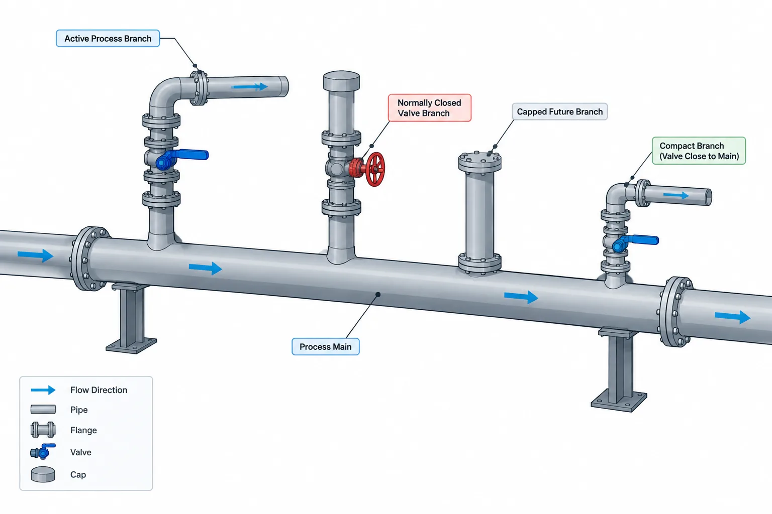
Dead legs in piping layout cannot be identified reliably from branch shape alone. A sound review must connect the physical arrangement with process flow, normal valve positions, equipment operating modes, drainage behavior, and the project’s acceptance criteria.
This guide explains how to distinguish stagnant branches from other piping conditions, establish meaningful measurement boundaries, review them in CAD, and document the resulting decisions. It is intended as a practical coordination resource rather than a substitute for project specifications, owner requirements, or discipline approval.
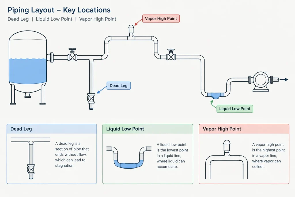
A dead leg is a section of piping in which fluid movement is absent, intermittent, or substantially lower than in the main flow path. It may be created by an unused branch, a normally closed valve, an instrument connection, a spare tie-in, or equipment that operates only occasionally. Although the geometry can look harmless in a CAD model, the trapped or poorly circulated volume may affect cleanliness, corrosion, freezing risk, sampling accuracy, temperature response, or product quality.
Not every branch is automatically a dead leg, and not every dead leg is prohibited. The practical task for a piping designer is to recognize potentially stagnant geometry, understand its function, and make it visible to the disciplines responsible for process, materials, operations, and code review. Acceptance criteria must come from the applicable project specification, process requirements, owner practices, and governing documents.
What makes a piping segment a dead leg?
A branch becomes a dead-leg concern when normal operation does not provide meaningful flow through the segment. The fluid may remain trapped continuously, move only during startup or maintenance, or exchange slowly with fluid in the active line.
Common examples include:
- A capped branch reserved for a future connection.
- A branch terminating at a normally closed isolation valve.
- A bypass that remains closed during routine operation.
- A drain or vent connection that is opened only occasionally.
- An instrument root-valve assembly extending away from the process line.
- A sample connection with infrequent use.
- A standby equipment branch isolated for long periods.
- An abandoned connection that was blinded rather than removed.
The operating state matters as much as the physical shape. A branch serving continuously operating equipment may have regular flow and therefore not behave as a dead leg. The same branch can become stagnant when the equipment is taken out of service or placed on standby.
Dead leg, dead end, and low point are not the same thing
These terms describe related but different conditions. Using them precisely improves design reviews and avoids vague comments.
| Term | Primary meaning | Typical concern |
|---|---|---|
| Dead leg | A segment with little, intermittent, or no routine circulation | Stagnation, contamination, corrosion, freezing, or delayed response |
| Dead end | A branch or run that terminates without a through-flow path | Often creates a dead leg, but its operating function still requires review |
| Low point | A geometric location where liquid can collect | Incomplete drainage, corrosion, freezing, or process hold-up |
| High point | A geometric location where gas or vapor can collect | Vapor locking, venting difficulty, or reduced liquid flow |
A horizontal capped branch can be a dead end and a dead leg without being a low point. Conversely, a sag in an active line can form a liquid pocket even though flow passes through it. Each condition should be evaluated and documented according to its actual mechanism.

Why dead legs matter
Fluid degradation and contamination
Trapped fluid may remain in the piping much longer than the bulk process stream. In services sensitive to residence time, cleanliness, biological growth, solids deposition, or cross-contamination, the stagnant volume can become a significant process concern.
Internal corrosion
A stagnant branch can create local conditions different from those in the flowing line. Deposits may settle, water may separate, treatment chemicals may not circulate effectively, and temperature may differ from the main process. Material selection alone does not establish that the geometry is acceptable.
Freeze and thermal exposure
Fluid in a dead leg may not receive the same thermal benefit as fluid moving through an adjacent line. Insulation and heat tracing can reduce exposure, but their effectiveness depends on the actual branch arrangement, fluid behavior, ambient conditions, and tracing layout.
Misleading instruments and samples
A long stagnant connection can delay the response of a pressure, temperature, analyzer, or sample point. The instrument may be correctly tagged and connected on the P&ID while its physical location produces a sample or indication that is not representative of current process conditions.
Drainage and flushing difficulty
A branch may be easy to fill but difficult to drain, flush, dry, or purge. Orientation, slope, valve location, and branch elevation all affect whether maintenance procedures can clear the trapped volume.
How dead-leg length is evaluated
Some projects evaluate a branch by comparing its stagnant length with a characteristic pipe diameter. However, there is no universal ratio or measurement convention that should be assumed for every service. The project must define both the allowable criterion and how the geometry is measured.
Potential measurement questions include:
- Does the length begin at the main pipe wall, branch centerline, fitting crotch, or fitting outlet?
- Does it end at a valve seat, valve face, cap, instrument diaphragm, or equipment boundary?
- Is the diameter based on nominal size, actual bore, branch bore, or another defined reference?
- Are valves and fittings included in the stagnant volume?
- Is the criterion based on centerline length, axial projection, or wetted flow path?
CAD geometry should not be used to declare compliance until these definitions are confirmed. A model can provide repeatable measurements, but it cannot decide which reference points the project intended.
Finding dead legs during CAD review
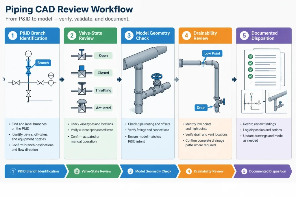
A reliable review starts with operating logic rather than an automatic search for capped lines. The reviewer should compare the P&ID, line list, valve states, equipment operating philosophy, and physical model.
Trace each branch to its function
Begin at the active process line and follow every branch to its endpoint. Identify whether it serves operating equipment, standby equipment, an instrument, a vent, a drain, a sample point, a bypass, or a future connection. Unidentified endpoints should be treated as unresolved design information.
Check normal valve positions
A valve can define the boundary between flowing and stagnant piping. Confirm which side of the closure retains process fluid and whether the valve is normally open, normally closed, locked, car-sealed, or operated only by procedure. Do not infer normal position from handle orientation in a generic model.
Review the actual bore path
The visible outside envelope does not show the full internal flow condition. Reduced ports, instrument passages, branch fittings, and valve cavities may affect the retained volume. Simplified CAD components are useful for layout, but detailed flow-path questions may require verified manufacturer information.
Check orientation and drainability
Review whether the branch rises, falls, or remains level from the active line. Determine where liquid or vapor would collect and whether the connection can be drained, vented, flushed, or purged as intended. A short branch can still create an undesirable pocket if it is oriented poorly.
Ways to reduce stagnant volume
The preferred solution depends on the reason for the branch. Practical options may include:
- Moving an isolation valve closer to the active line.
- Removing an unnecessary branch rather than capping it.
- Shortening an instrument or sample connection.
- Reorienting the branch to improve drainage or venting.
- Providing an engineered flushing, purge, circulation, or drain arrangement.
- Locating a future tie-in so the retained volume is minimized.
- Revising the operating arrangement so the branch receives routine flow.
Placing a valve close to the main line is not automatically the complete answer. Access, operability, weld clearance, insulation, maintenance removal, valve type, and process function must still be coordinated.
How to document dead-leg decisions
The P&ID should communicate process function, valve state, and the purpose of the branch. The 3D model and arrangement drawings should establish physical location and orientation. Isometrics should provide fabrication geometry, while review records should capture why a questionable branch was accepted, shortened, relocated, or removed.
Useful CAD and review data may include:
- A unique review marker linked to the affected branch.
- The line number and branch service.
- The endpoint type and normal operating condition.
- Defined start and end points for any reported measurement.
- The source of the project acceptance criterion.
- The responsible discipline and disposition status.
- A note when vendor internals or field conditions require verification.
Avoid placing unsupported statements such as “dead leg acceptable” directly on a drawing. Instead, reference the verified project criterion or approved review disposition through the project’s normal document-control process.
A practical review checklist
- Identify every branch that lacks continuous routine flow.
- Confirm the branch purpose from controlled process documents.
- Verify normal valve states and realistic operating modes.
- Locate the true stagnant boundary, not merely the visible endpoint.
- Check slope, drainage, venting, flushing, and purge capability.
- Review instrument and sample connections for response and representativeness.
- Confirm the project’s measurement convention before calculating a ratio.
- Coordinate access, fabrication, insulation, and maintenance before shortening geometry.
- Record the disposition so the issue does not reappear at each review stage.
Model geometry supports the decision but does not replace it
Dead-leg review connects process intent with physical piping layout. CAD can reveal branch length, elevation, orientation, valve placement, and nearby access constraints, but it cannot determine the operating state or acceptance criterion by geometry alone. The best workflow combines controlled process information, clear measurement rules, disciplined modeling, and documented multidisciplinary review.
Turn dead-leg findings into coordinated design actions
A useful dead-leg review should state more than the presence of a capped or isolated branch. It should explain the operating condition that creates stagnation, identify where the stagnant region begins and ends, and assign the question to the discipline able to resolve it. This prevents layout comments from being treated as process approvals.
Separate observations from acceptance decisions
The piping reviewer can identify geometry, orientation, valve location, access constraints, and likely collection points. Process, materials, operations, instrumentation, and other responsible disciplines may need to determine whether the condition is acceptable. Review records should distinguish verified facts from assumptions and pending decisions.
Recheck branches after design changes
A branch that was acceptable in an earlier model can become stagnant after a valve is relocated, equipment duty changes, a bypass is added, or a connection is abandoned. Dead-leg review should therefore be included in change management rather than treated as a one-time model check.
Carry the disposition into project deliverables
When a branch is retained, shortened, removed, or assigned a flushing or operating requirement, the approved outcome should appear in the appropriate controlled documents. Consistent information across the P&ID, model, isometric, line data, and review record helps prevent the original concern from returning during fabrication, commissioning, or later modification.
Frequently asked questions about piping dead legs
Is every capped branch a dead leg?
A capped branch commonly contains stagnant fluid, but its significance depends on service, orientation, operating history, and project requirements. The branch should be reviewed rather than classified solely from its endpoint.
Where should dead-leg measurement begin?
The starting point must follow the project’s defined convention. Depending on that convention, the reference may relate to the main run, branch fitting, flow boundary, or another specified location. The chosen point should be recorded with the measurement.
Does moving a valve closer to the main line eliminate the concern?
It can reduce retained volume, but it does not automatically resolve drainage, valve-cavity, access, maintenance, insulation, or fabrication concerns. The revised arrangement still requires multidisciplinary review.
Can a flowing branch become a dead leg?
Yes. A branch may circulate during one operating mode and become stagnant when equipment is on standby, a valve is closed, or the process configuration changes. Review should consider credible operating states rather than only the design flow case.
Can CAD software determine whether a dead leg is acceptable?
CAD can support detection and repeatable measurement, but it cannot establish process intent or select the governing acceptance criterion. Those decisions depend on controlled project information and responsible discipline review.
How should an uncertain branch be marked?
Use the project’s review or issue-tracking method to identify the branch, its service, the suspected stagnant boundary, the unresolved question, and the responsible discipline. Avoid placing an unsupported acceptance statement on a controlled drawing.