Tag: piping layout

  • Y-Strainers vs. Basket Strainers in Piping CAD: Orientation, Access, and Detailing

    Y-Strainers vs. Basket Strainers in Piping CAD: Orientation, Access, and Detailing

  • Check Valve Types in Piping CAD: Flow Direction, Orientation, and Maintenance

    Check Valve Types in Piping CAD: Flow Direction, Orientation, and Maintenance

  • Pipe Shoes, Saddles, and Wear Pads in CAD: Geometry, Contact, and Documentation

    Pipe Shoes, Saddles, and Wear Pads in CAD: Geometry, Contact, and Documentation

  • Piping CAD Model Levels of Detail: Matching Geometry to Design Purpose

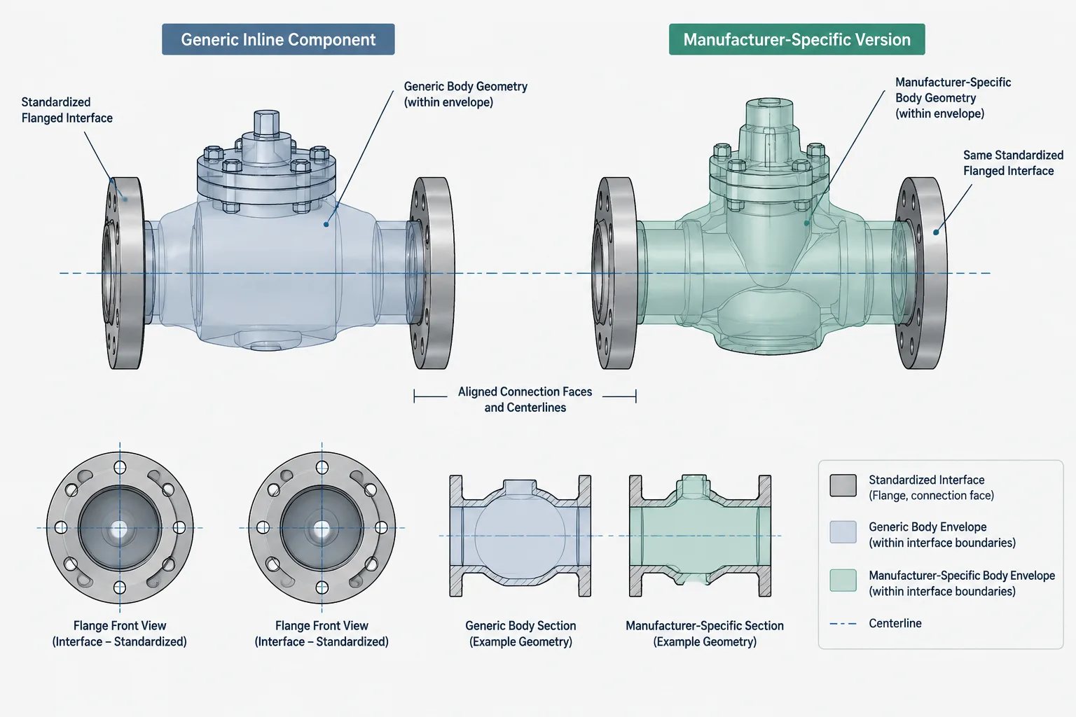
    Piping CAD Model Levels of Detail: Matching Geometry to Design Purpose

  • Reducing Tee vs. Equal Tee and Reducer: A Practical Piping Layout Comparison

    Reducing Tee vs. Equal Tee and Reducer: A Practical Piping Layout Comparison

  • Pipe Centerline Spacing in CAD: How to Account for Insulation, Flanges, Valves, and Access

    Pipe Centerline Spacing in CAD: How to Account for Insulation, Flanges, Valves, and Access

  • Grooved Pipe Connections in CAD: Couplings, End Gaps, and Cut-Length Control

    Grooved Pipe Connections in CAD: Couplings, End Gaps, and Cut-Length Control

  • Pipe Unions vs. Couplings in Piping CAD: Assembly, Maintenance, and Cut-Length Control

    Pipe Unions vs. Couplings in Piping CAD: Assembly, Maintenance, and Cut-Length Control

  • Orifice Flanges and Meter Runs in Piping CAD: A Practical Layout and Detailing Guide

    Orifice Flanges and Meter Runs in Piping CAD: A Practical Layout and Detailing Guide