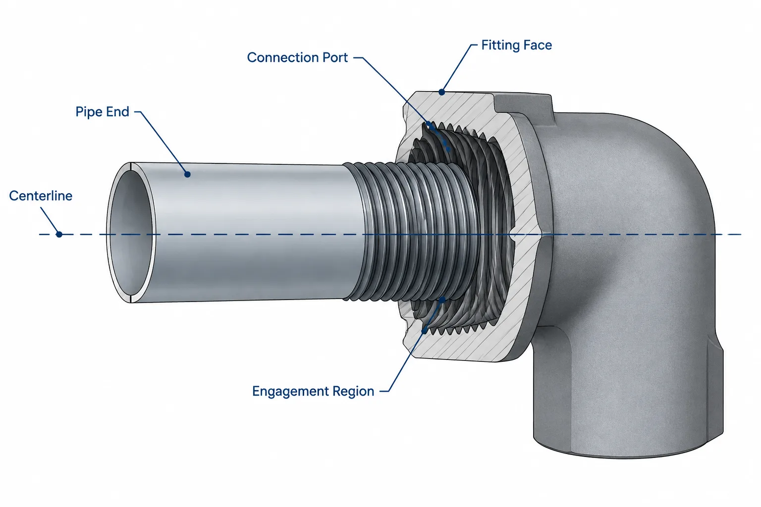
Threaded pipe joints in CAD require more than centerline alignment and visually correct component placement. The model must distinguish the fitting face, connection port, assumed pipe-end position, and final installed orientation. If those references are treated as interchangeable, an assembly can appear correct while producing an unreliable pipe cut length.
This guide explains how engagement and wrench makeup affect modeled geometry, why threaded fittings need controlled connection data, and which assumptions should be verified before dimensions or cut lists are released.
Threaded piping can look simple in a CAD model: place two components on the same centerline and move the pipe end into the fitting. The difficulty is deciding how far the parts should overlap. A threaded joint does not normally have a single visible mating plane equivalent to the face of a flange or the end of a butt-weld fitting.
The installed position depends on the thread form, dimensional tolerances, surface condition, sealant, assembly method, and the amount of wrench makeup. As a result, a perfectly constrained CAD assembly can still predict the wrong exposed pipe length or fitting location if its connection points do not reflect the intended threaded engagement.
Designers do not need to model every thread to produce useful piping layouts. They do need a consistent method for locating component ports, calculating cut lengths, and identifying dimensions that require confirmation from a governing standard, project specification, manufacturer, or fabricator.
What thread engagement means
Thread engagement is the axial distance over which the external thread of one component enters the internal thread of another. In common threaded piping, the external thread may be on a pipe, nipple, plug, or male-ended component. The internal thread may be in a coupling, elbow, tee, valve, union end, or other fitting.
Engagement should not be confused with the total threaded length visible on a loose component. Some external threads may remain exposed after assembly, while other portions of the thread participate in tightening and sealing. The resulting installed position is therefore not established merely by aligning the end of a pipe with the outer face of a fitting.
For tapered pipe threads, tightening progressively increases interference between the mating threads. This makes the final position sensitive to assembly conditions. Parallel threaded systems rely on different sealing and positioning arrangements, so their CAD behavior should not automatically be treated as identical to tapered-thread behavior.
Hand-tight engagement and wrench makeup
Threaded-joint terminology often separates initial hand engagement from additional wrench tightening. These concepts are useful for understanding assembly, but they should not be converted into universal CAD dimensions without verified data.
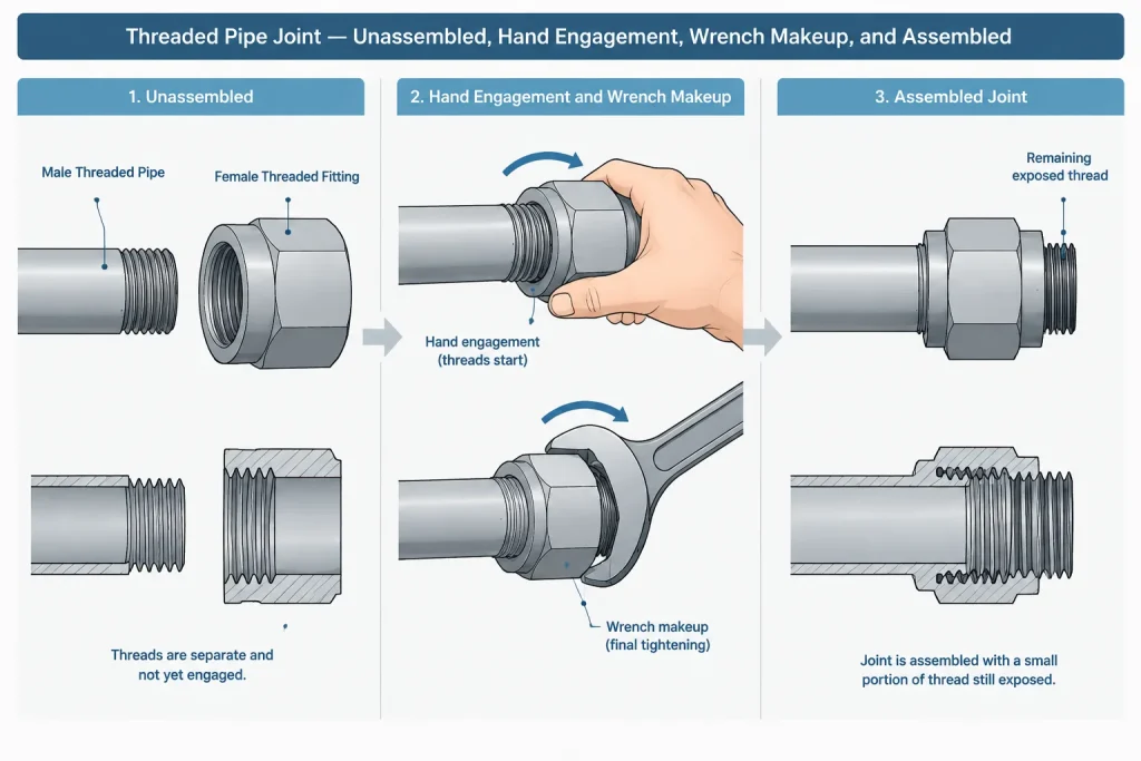
- Hand-tight engagement describes the position reached before substantial wrench force is applied.
- Wrench makeup is the additional rotation and axial advancement produced during tightening.
- Final installed engagement is the resulting assembled position, subject to thread tolerances, sealant, component condition, and workmanship.
A model library may use a nominal installed engagement to place components and estimate cut lengths. That value is a design convention, not a guarantee that every field-assembled joint will stop at the same axial position or rotational orientation.
Why fitting faces are unreliable cut-length references
Many threaded fittings have a clearly modeled outer face at each opening. It is tempting to dimension pipe length from face to face and then subtract nothing for the joint. That method ignores the portion of pipe entering the fitting.
The opposite mistake is to subtract the full depth of the fitting socket or threaded recess. The pipe may not reach the geometric bottom of that recess, and forcing the model to do so can shorten the calculated cut piece.
A better CAD definition uses separate reference locations:
- Component center or theoretical intersection: used to position elbows, tees, and branches.
- Visible end face: represents the exterior limit of the fitting body.
- Connection port: controls where the mating component is placed.
- Nominal pipe-end position: represents the assumed end of the pipe inside the assembled joint.
These locations may coincide in simplified symbols, but they should remain conceptually distinct. A CAD port placed on the visible fitting face may be convenient for snapping geometry together, yet it cannot calculate a reliable threaded pipe cut length unless engagement is handled elsewhere in the component data.
A practical threaded cut-length concept
For a straight threaded pipe piece between two components, the physical cut length is generally longer than the visible distance between the fitting faces because each pipe end enters a mating component.
Conceptually, the relationship is:
Pipe cut length = exposed distance between fitting faces + engagement at the first end + engagement at the second end
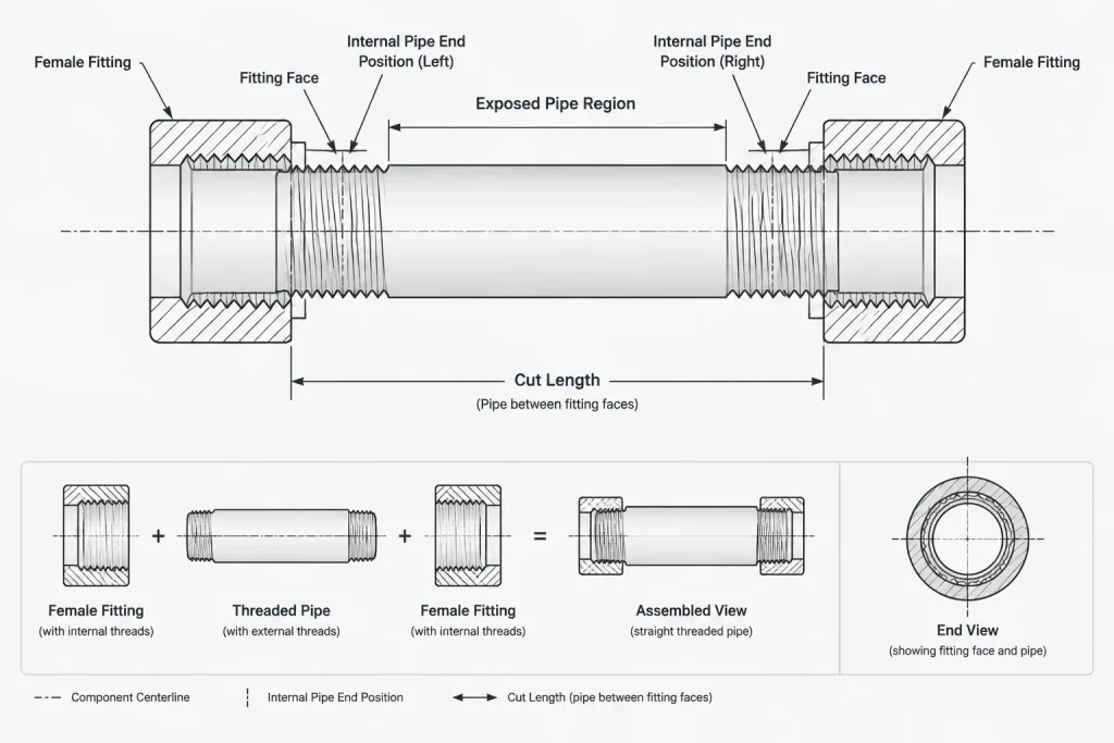
If the layout is dimensioned from fitting centerlines or theoretical intersections, the fitting geometry must also be included. The workflow then becomes:
- Establish the controlled centerline or component reference points.
- Determine the distance from each reference point to its external opening face.
- Determine the approved nominal engagement assumption for each joint.
- Calculate the pipe-end coordinates inside the fittings.
- Measure between those pipe-end coordinates to obtain the modeled cut length.
The engagement at both ends should not automatically be assumed equal. The connected components may use different end constructions, and a valve or specialty item may have manufacturer-specific internal geometry.
Rotational orientation creates another variable
A threaded elbow, tee, valve, instrument root connection, or drain component often must finish in a particular orientation. Axial engagement and rotational position are linked: turning the component changes both its clocking and its insertion depth.
This is especially important where the final orientation controls a branch direction, valve operator position, instrument readability, drain direction, or access clearance. A rigid CAD constraint can show the exact desired orientation without revealing whether that orientation is realistically obtainable at the assumed engagement.
Design documentation should therefore distinguish between design intent and guaranteed assembly position. Where clocking is critical, the designer may need an adjustable connection arrangement, a union, a flanged break, a manufacturer-confirmed component, or a field-fit instruction rather than reliance on thread tightening alone.
How much thread geometry should be modeled?
Detailed helical threads are rarely necessary for general piping layout. They increase model complexity without resolving assembly tolerance. Most projects benefit from one of three representation levels.
| Representation | Typical use | Main limitation |
|---|---|---|
| Centerline and symbolic end | P&IDs, diagrams, and early routing | Does not support physical cut-length calculation |
| Simplified body with defined ports | Plant layout, coordination, and material extraction | Requires verified port and engagement conventions |
| Detailed thread envelope or cosmetic thread | Close-up fabrication details and interference review | May imply more assembly precision than the joint provides |
Even in a detailed model, the important data are the connection type, nominal size, thread designation, port axis, engagement convention, and source of the component dimensions. A realistic-looking thread without controlled metadata can be less useful than a simple model with well-defined connection points.
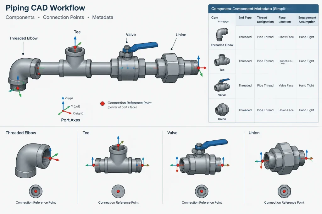
CAD library fields worth controlling
A threaded component library should store enough information to distinguish geometry from assembly assumptions. Useful fields include:
- Nominal connection size and applicable size system.
- Male or female end designation.
- Thread form or connection specification.
- Port axis and insertion direction.
- External face location.
- Nominal installed engagement used by the model.
- Component center-to-face or end-to-end geometry.
- Manufacturer or generic dimensional source status.
- Whether cut-length extraction is permitted from the object.
Generic library parts should be labeled accordingly. If a valve, union, instrument fitting, or specialty component has manufacturer-dependent dimensions, replacing a generic object with the selected item should trigger a dimensional review.
Thread sealant and assembly condition
Thread sealant is part of the joint assembly process, but it should not be represented as a fixed axial spacer unless the connection design specifically uses a separate sealing element that establishes position. Compounds and tapes can affect friction and tightening behavior, yet they do not create a universally predictable modeled gap.
Coatings, plating, thread damage, reused components, and manufacturing tolerances can also change the final makeup. CAD should not attempt to conceal these variables with false geometric precision. Instead, drawings and fabrication procedures should identify the required connection system and leave assembly acceptance to the applicable specification and inspection process.
A review workflow for threaded piping
Before releasing a threaded piping model or drawing, perform a focused connection review:
- Confirm that male and female ends are compatible.
- Verify that component ports are not merely located on cosmetic faces.
- Check that pipe cut lengths include the intended engagement at both ends.
- Review elbows, tees, valves, and instruments for critical clocking.
- Identify components whose overall dimensions depend on a selected manufacturer.
- Confirm that unions or other break points allow practical assembly and removal.
- Avoid dimensioning both the exposed pipe length and the overall component spacing if the dimensions could conflict.
- Mark field-fit or verify-in-field conditions where installed orientation or existing geometry controls the result.
Use CAD engagement as a controlled assumption
The most useful threaded piping model is not the one with the most detailed threads. It is the one that clearly separates fixed component geometry from assumed joint makeup.
Use verified dimensional references for fitting bodies and end preparations, define a consistent nominal engagement method, and document where actual assembly can vary. This approach improves cut lists, reduces unexplained model overlaps, and prevents a visually precise CAD joint from being mistaken for a guaranteed field-installed position.
Turning the model assumption into usable documentation
A nominal engagement value is most useful when its purpose and source are visible to everyone relying on the model. The CAD object, project library, drawing notes, and material workflow should use compatible definitions rather than leaving each designer to interpret the fitting geometry independently.
When reviewing a threaded assembly, separate the information into three categories:
- Controlled geometry: component centerlines, body dimensions, opening faces, and port axes established by the selected dimensional source.
- Assembly assumptions: modeled engagement, pipe-end location, and any expected relationship between makeup and orientation.
- Items requiring confirmation: manufacturer-dependent geometry, critical clocking, field-fit conditions, and connections governed by project fabrication requirements.
This separation helps prevent a nominal CAD assumption from being carried into fabrication as though it were a guaranteed stopping position.
Cut-list quality checks
Before using model data for cutting or procurement, verify that the reported pipe length represents the physical end-to-end cut piece rather than only the exposed segment. Also confirm that engagement has not been included twice through both port offsets and a separate cut-length rule.
Changes to fittings, valves, unions, or specialty components should prompt a new dimensional review. Two objects may share a connection description while using different body geometry or port definitions. Replacing an object without recalculating adjacent pipe can therefore preserve the routing centerline but alter the intended cut piece.
Drawing communication for uncertain assembly position
Where actual makeup can affect location or clocking, drawings should communicate design intent without implying unattainable precision. Appropriate documentation may identify a field-fit connection, a required final orientation, a controlled overall location, or a need for confirmation from the selected component source.
The goal is not to remove assembly variation from the model. It is to make the variation visible, keep it out of fixed geometry, and prevent conflicting dimensions from controlling the same threaded run.
Frequently asked questions
Should a threaded pipe end stop at the fitting face in CAD?
Not when the model is intended to support physical cut-length calculations. The fitting face is an exterior geometric reference, while the pipe end normally occupies an assumed position inside the threaded connection.
Is thread engagement the same as wrench makeup?
No. Engagement describes the axial overlap of mating threads. Wrench makeup describes additional tightening after initial hand engagement and contributes to the final assembled position.
Can the bottom of a modeled threaded recess be used as the pipe-end location?
Only when that location is supported by the applicable component and connection data. A cosmetic recess or internal cavity should not automatically be treated as the installed pipe-end position.
Why can a correctly aligned threaded valve still create a layout problem?
Alignment does not prove that the required operator or body orientation can be reached at the assumed makeup. Rotation and axial advancement are linked in a threaded connection, so critical clocking requires a separate review.
Do detailed modeled threads improve cut-length accuracy?
Not by themselves. Cut-length accuracy depends on verified component geometry, controlled ports, a documented engagement convention, and consistent extraction rules. Detailed thread graphics can remain purely visual.
When should a generic threaded CAD component be replaced?
Replace or review it when the selected component has manufacturer-dependent body or end geometry, when orientation is critical, or when the model will be used for fabrication-level dimensions and cut data.