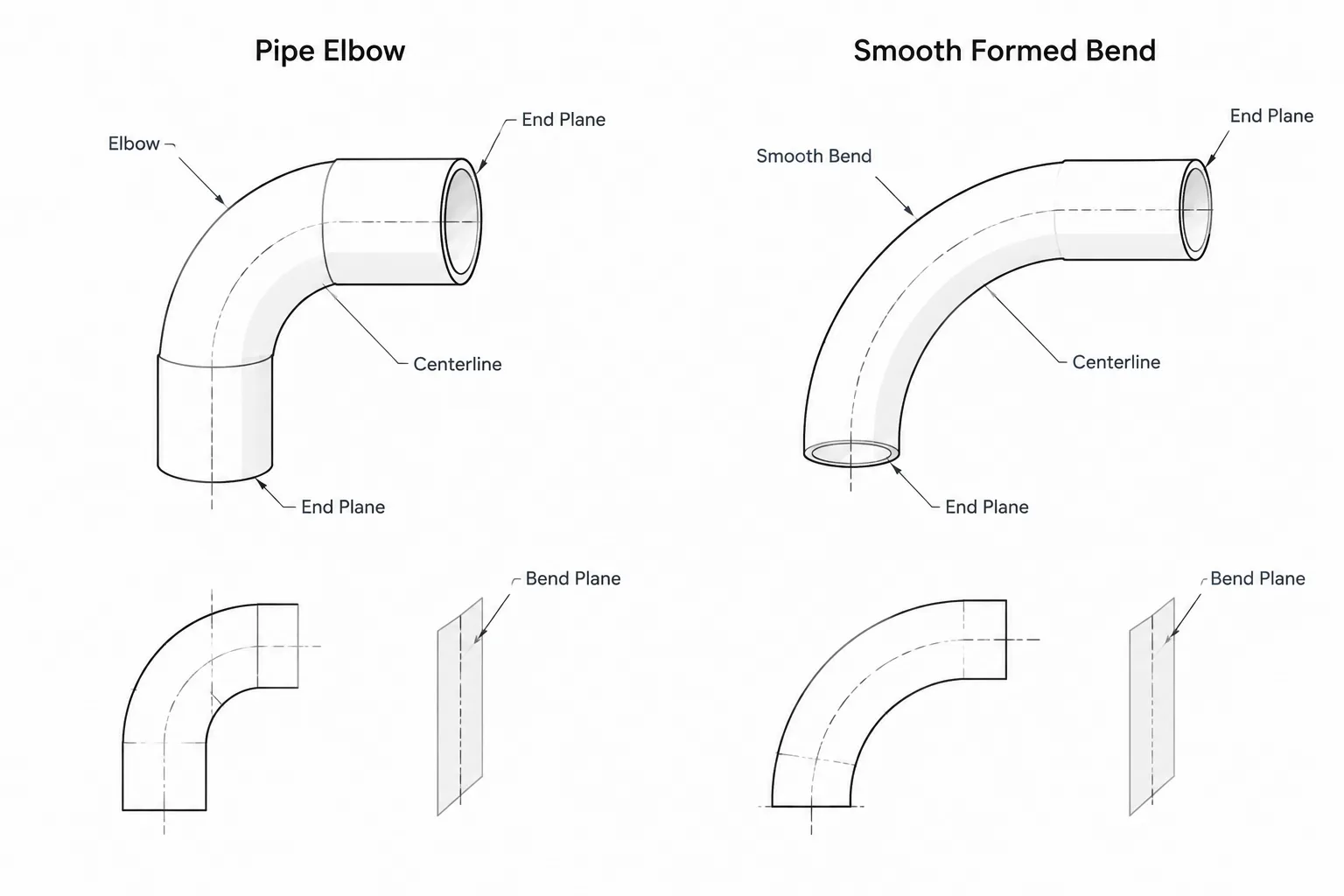
Pipe bends vs. elbows in CAD is not merely a question of how a directional change looks on screen. The selected object type determines where straight pipe ends, how joints are represented, which references control the route, and how the item appears in fabrication and material outputs.
This guide explains how to distinguish a discrete elbow fitting from formed pipe, with emphasis on centerline geometry, tangent points, physical end planes, fabrication feasibility, and drawing communication. Project specifications, approved catalogs, and qualified fabrication requirements remain the controlling sources for final selection.
Pipe bends and pipe elbows can change a line in the same general direction, but they are not automatically interchangeable components. An elbow is typically a discrete fitting with defined connection points and catalog dimensions. A bend is commonly formed from pipe or tube, with its geometry controlled by a bend radius, bend angle, tangent points, and fabrication method.
The distinction matters when developing a piping model, calculating straight-pipe cut lengths, preparing an isometric, or replacing one routing option with another. A centerline that looks correct in plan view may still represent the wrong material item, occupy the wrong space, or omit fabrication information needed by the shop.
What is a pipe elbow?
A pipe elbow is a fitting installed between adjoining pipe segments to change direction. Its size, connection type, material description, wall designation, angle, and dimensional basis are normally selected through the project piping specification or an approved component catalog.
Depending on the piping system, an elbow may have butt-weld, socket-weld, threaded, flanged, or other recognized end connections. The fitting has identifiable ends, and its placement is generally controlled by fitting reference points such as end planes, centerline intersections, and center-to-end dimensions.
In CAD, an elbow is usually treated as an individual component. It receives a catalog identity and can appear as a separate item in a material takeoff or bill of materials. The connected straight pipe stops at the elbow end planes rather than continuing through the fitting.
What is a pipe bend?
A pipe bend is a curved length produced by forming straight pipe or tube. The bend may be made by cold bending, hot bending, induction bending, or another qualified process appropriate to the material and project requirements. The resulting item can include the curved portion as well as straight tangent lengths at one or both ends.
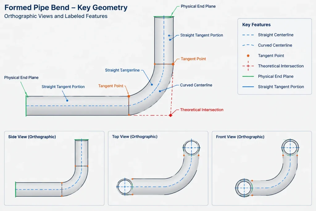
A bend is defined by more than its angle. Important geometric and fabrication information can include:
- Nominal pipe size and selected wall or material description
- Centerline bend radius
- Total change in direction
- Locations of the tangent points
- Straight tangent requirements at the ends
- Bend plane and rotational orientation
- End preparations and final end-to-end dimensions
- Permitted ovality, wall variation, and dimensional tolerances
- Heat treatment, examination, or testing requirements when specified
These requirements should come from the governing design documents, project specification, approved bending procedure, and applicable standards. A generic CAD arc does not establish that a bend can be fabricated from the selected pipe.
Pipe bends vs. elbows: practical differences
| Topic | Elbow | Pipe bend |
|---|---|---|
| Product concept | Separate piping fitting | Pipe or tube formed into a curved shape |
| Geometry control | Catalog or specified fitting dimensions | Radius, angle, tangent points, tangents, and final end locations |
| Material reporting | Usually listed as a fitting item | May be listed as a fabricated bend, bent pipe item, or part of a spool |
| Routing flexibility | Limited to available fitting configurations | Can permit project-specific radius and angle where fabrication allows |
| Wall behavior | Controlled through the fitting product specification | Forming can affect wall thickness and cross-sectional shape |
| CAD replacement | Inserted as a defined component | Requires verified bend geometry and fabrication data |
| Drawing emphasis | Ends, angle, orientation, and fitting identity | Radius, tangent points, bend plane, angle, ends, and inspection requirements |
These are general distinctions rather than purchasing rules. Some systems use manufacturer-produced bends as catalog components, while some elbows are custom or segmented products. The project commodity description remains the controlling source.
Why a bend is not simply a large-radius elbow
It is tempting to classify any broad curve as an elbow with a larger radius. That shortcut can create errors because an elbow and a formed bend may use different dimensional references and procurement descriptions.
For an elbow, the designer commonly locates the fitting by its ports and catalog takeout. For a bend, the designer may need to locate both tangent points and establish the curve between them. If straight tangents are part of the fabricated bend, the item ends can lie beyond the tangent points. Therefore, the curved section, theoretical tangent intersection, and physical end planes are not necessarily the same references.
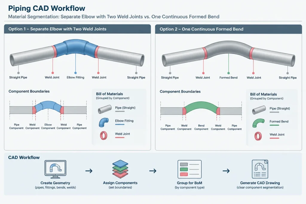
The distinction also affects material quantities. Modeling a formed bend as an elbow plus two straight pipe segments may produce the desired external route but the wrong item breakdown. Conversely, modeling a catalog elbow as one continuous bent pipe object may hide fitting welds and generate an incorrect cut list.
Wall thickness, ovality, and bend feasibility
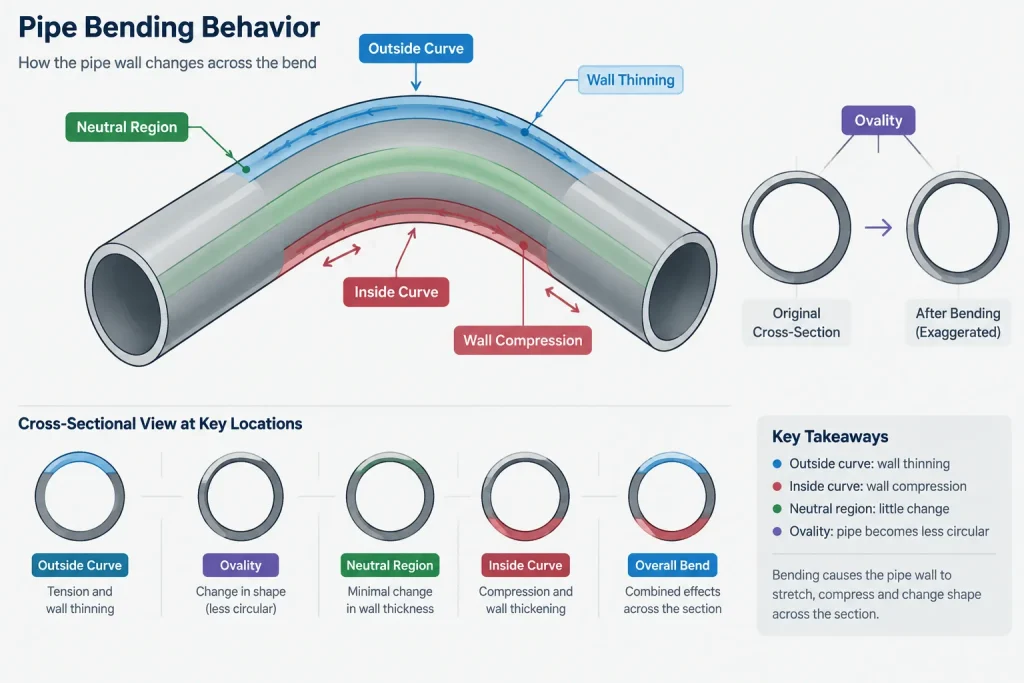
Forming a pipe bend changes the geometry of the original pipe. The outside of the curve is stretched, the inside is compressed, and the cross section can depart from an ideal circle. The amount and location of these effects depend on factors such as material, original wall, bend radius, forming process, tooling, and procedure controls.
A nominal CAD solid normally does not predict the finished minimum wall or actual ovality. Modeling the bend at nominal dimensions is useful for layout, but it should not be interpreted as proof that the formed component satisfies design requirements.
Before a custom bend is accepted, the responsible disciplines may need to verify:
- Whether the selected material and wall can be formed by the proposed process
- Whether the finished wall remains adequate for the design basis
- Whether the bore and outside envelope meet project limits
- Whether the ends provide enough straight length for forming, clamping, welding, or examination
- Whether post-forming heat treatment or examination is required
- Whether the fabricator can achieve the specified radius, angle, and end orientation
Centerline geometry and tangent points
The most useful way to define a simple planar bend in CAD is usually by its centerline radius, included directional change, and tangent points. A tangent point marks where the straight centerline transitions into the curved centerline. Extending the two straight centerlines produces a theoretical intersection, but that intersection is not a physical corner on the bend.
This difference is important when dimensioning. A dimension to the theoretical intersection may help establish routing geometry, while a dimension to an end plane controls where another component or weld is located. Those dimensions should not be substituted for one another.
For a bend that changes direction in more than one view, the bend plane and rotation must also be controlled. A correct radius and angle can still produce the wrong endpoint if the bend is rotated about the incoming pipe axis.
CAD workflow for selecting and modeling the component
1. Confirm the intended commodity
Determine whether the line class calls for a catalog elbow, a fabricated bend, or permits either option. Do not infer this solely from the shape shown on a preliminary layout.
2. Establish controlling references
For an elbow, use verified fitting dimensions and connection ports. For a bend, identify the radius, tangent points, bend angle, bend plane, straight tangents, and physical end planes.
3. Model the correct material breaks
Place welds or other joints where they actually occur. A continuous bent section should not contain artificial fitting welds, and a separate elbow should not be merged visually into adjacent pipe if the model supports component-level reporting.
4. Check the full envelope
Evaluate the outside pipe surface, insulation where applicable, nearby supports, structural steel, equipment, and access zones. A wider bend radius may reduce abrupt routing but consume more layout space than an elbow.
5. Verify outputs
Review the isometric, bill of materials, cut list, spool breakdown, weld list, and extracted coordinates. A visually correct model can still produce incorrect fabrication data if the component type or reference points are wrong.
Drawing information for fabricated bends
A fabrication drawing should communicate enough information to define the bend without requiring the shop to measure a rendered curve. Depending on the project workflow, useful information can include:
- Pipe material, size, wall designation, and item identification
- Centerline radius and bend angle
- Tangent-point locations or dimensions
- Required straight tangents
- End-to-end or coordinate dimensions
- Bend plane, rotation, and orientation marks
- End preparations and connection details
- Applicable fabrication, inspection, and tolerance references
Avoid controlling the same endpoint through multiple redundant dimension chains. Dimensions should make the intended geometry inspectable without creating conflicts between radius, angle, coordinates, and overall length.
When each option may be useful
Elbows are often practical where standard component availability, compact routing, predictable takeout, and straightforward replacement are priorities. Formed bends may be considered where a broader change in direction, reduced fitting count, special routing angle, or continuous-flow path is desirable.
Selection is not based on appearance alone. Space, stress analysis, flow considerations, fabrication capability, material availability, inspection, transport, installation, maintenance, and project specifications can all influence the decision. Any substitution should be reviewed by the responsible engineering and materials functions rather than made as a drafting convenience.
Key takeaway
Pipe bends and elbows both redirect piping, but they represent different geometry, fabrication, and documentation concepts. An elbow is generally modeled and reported as a fitting with verified component dimensions. A formed bend must be controlled through its radius, angle, tangent geometry, end locations, orientation, and fabrication requirements. Keeping that distinction clear helps the CAD model support accurate routing, material reporting, spool detailing, and shop communication.
Model-review checklist before drawing issue
A focused review should confirm that the modeled geometry and the documented commodity describe the same physical item. This is especially important when a preliminary routing arc has been replaced by a specification-driven component or a shop-fabricated bend.
- Component classification: Confirm whether the object is reported as an elbow fitting, a fabricated bend, bent pipe, or part of a spool.
- Geometric references: Distinguish the theoretical centerline intersection, tangent points, connection ports, and physical end planes.
- Material boundaries: Check that straight-pipe limits and actual joints agree with the intended fabrication arrangement.
- Orientation: Verify the bend plane and rotation, not only the apparent angle in a single view.
- Space claim: Review the complete outside envelope and any project-required allowances rather than relying on the centerline alone.
- Extracted information: Compare the model against the isometric, material report, cut list, spool information, weld list, and endpoint coordinates.
- Fabrication definition: Ensure that a formed bend carries the radius, tangent, end, orientation, and process-related information required by the approved workflow.
Managing substitutions during design development
Changing an elbow to a bend, or a bend to an elbow, should be treated as a component and routing revision rather than a graphical cleanup. The change can move end planes, alter straight-pipe cut lengths, change joint locations, affect the occupied envelope, and revise material reporting.
After a substitution, downstream deliverables should be regenerated and reviewed. Retaining the old dimensions or material identity while changing only the visible curve can leave the drawing, model database, and fabrication package describing different arrangements.
Frequently asked questions
Does a smooth CAD arc automatically represent a fabricated pipe bend?
No. An arc establishes graphical geometry, but it does not define the material item, forming process, straight tangents, end preparations, tolerances, or fabrication feasibility. Those requirements must come from the applicable project documents and approved procedures.
Why are tangent points important when modeling a bend?
Tangent points identify where the straight centerline transitions into the curved centerline. They help control the bend geometry and straight-pipe limits, but they are not automatically the physical ends of a fabricated item.
Can an elbow and a bend share the same visible centerline route?
They can appear similar in a layout while representing different component boundaries, joints, end locations, envelopes, and material records. A visual match does not establish interchangeability.
What commonly causes cut-length errors when replacing an elbow with a bend?
Errors often result from confusing elbow end planes with bend tangent points, overlooking straight tangents included with the bend, or failing to update the limits of adjoining straight pipe.
Should elbows and fabricated bends use the same material-reporting identity?
Not by assumption. An elbow is generally reported as a fitting, while a bend may be identified as bent pipe, a fabricated bend, or part of a spool. The project commodity description and reporting rules control the correct identity.
Is centerline geometry enough for clash review?
No. The review should consider the physical pipe or fitting envelope and any applicable project allowances, nearby supports, structures, equipment, and access requirements.