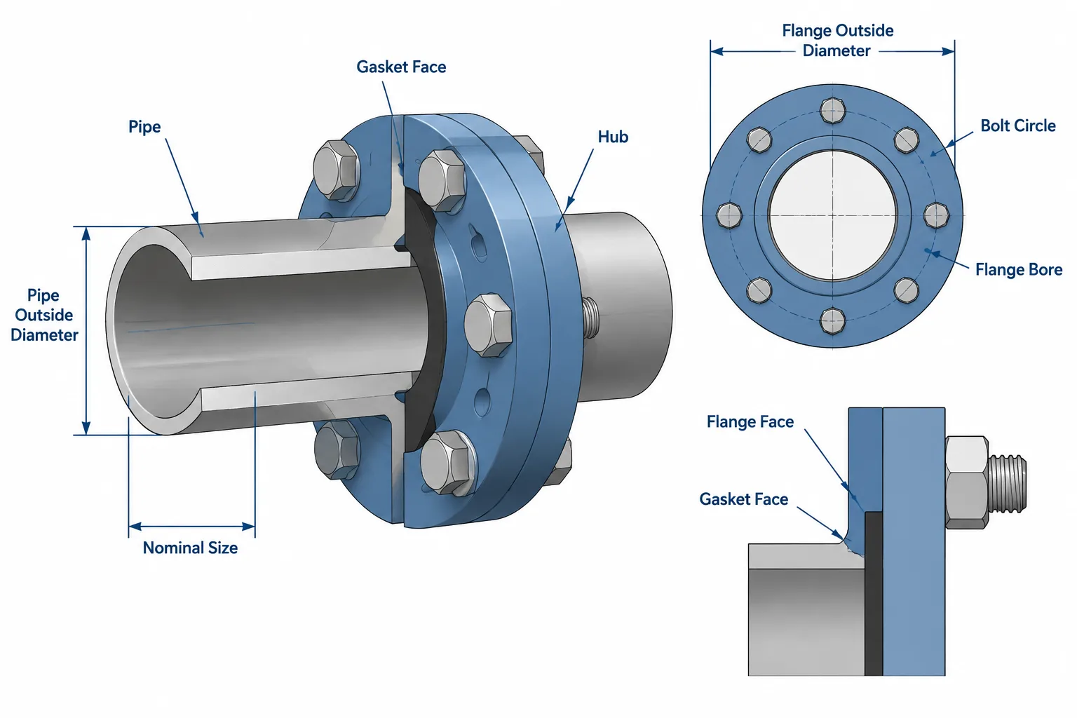
Flange size vs. pipe size is a common source of confusion because the nominal designation identifies a piping connection rather than one measurable diameter. Pipe outside diameter, flange bore, flange outside diameter, and bolt-circle geometry describe different parts of the assembly.
This guide explains how those terms relate and why nominal size alone cannot confirm that a flange fits the pipe, matches another flange, or represents the correct component in a CAD model.
A flange described as a certain pipe size is not expected to have the same outside diameter as the connected pipe. The size designation normally identifies the nominal piping connection, while the flange outside diameter, thickness, bolt circle, hole pattern, hub geometry, and bore are separate dimensions.
This distinction is important when selecting components, reviewing vendor data, building CAD libraries, or checking whether two flanges can be assembled. Matching the nominal pipe size is necessary, but it is not enough to establish flange compatibility.
What Flange Size Usually Means
In a piping specification or component description, flange size generally refers to the nominal size of the piping connection. In a U.S.-based system, this is commonly expressed as Nominal Pipe Size, or NPS. Metric-oriented documentation may use a DN designation.
NPS and DN are nominal identifiers rather than measured flange diameters. A flange carrying an NPS designation is intended for use within the corresponding nominal piping system, subject to its flange type, pressure class, material specification, dimensional standard, facing, and bore requirements.
For example, the nominal size does not directly state any of the following:
- The actual pipe outside diameter
- The pipe inside diameter
- The flange outside diameter
- The flange bore diameter
- The bolt-circle diameter
- The number or diameter of bolt holes
- The flange thickness
Those values must be obtained from the applicable dimensional data and project specification.
Why Flange Outside Diameter Is Larger Than Pipe Outside Diameter
A bolted flange joint needs room for the gasket seating region, bolt holes, structural flange body, and any hub or neck that transfers load into the connected pipe. Its outside diameter is therefore established by joint geometry rather than by simply extending the pipe wall outward.
The flange body must also accommodate a particular pressure-class family and flange design. Consequently, two flanges for the same nominal pipe size may have different outside dimensions if they belong to different pressure classes or dimensional systems.
This is why a CAD designer should not create a flange by taking a pipe cylinder and applying an arbitrary scale factor. The body diameter, bolt pattern, thickness, facing, and hub profile are controlled dimensions that must come from verified component data.
Pipe OD and Flange Bore Serve Different Purposes
Pipe outside diameter defines the external cylindrical surface of the pipe. For many commonly used nominal pipe sizes, the outside diameter remains associated with the nominal size while schedule changes the wall thickness and inside diameter.
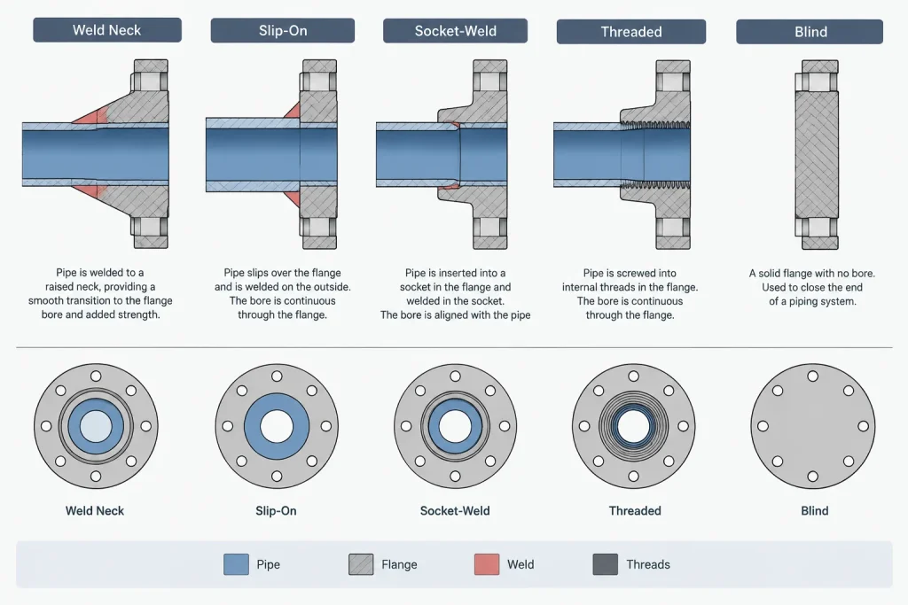
Flange bore is the opening through the flange. Its relationship to the pipe depends on the flange type and intended attachment.
Weld Neck Flanges
A weld neck flange has a tapered hub and a butt-weld end. Its bore may need to correspond to the connected pipe wall so that the transition through the weld area is suitable for the specified assembly. Selecting only by nominal size and pressure class can leave the bore definition incomplete.
CAD libraries should therefore avoid treating one generic weld neck flange as automatically valid for every schedule. If bore variants matter to procurement or fabrication, they should be represented through separate catalog entries, controlled parameters, or verified manufacturer geometry.
Slip-On Flanges
A slip-on flange is assembled over the pipe, so its bore must permit the pipe outside diameter and relevant fabrication clearance. The flange bore is not the same as the pipe inside diameter.
In a simplified model, the internal clearance may not be visible. Nevertheless, the attachment method affects pipe insertion, weld locations, cut length, and the flange’s axial position.
Socket-Weld Flanges
A socket-weld flange accepts the pipe into an internal socket. The socket geometry, pipe stop, bore, and assembly detail are distinct from those of a slip-on or weld neck flange. A generic flange solid with the correct bolt pattern may be inadequate for fabrication-level work.
Threaded Flanges
A threaded flange has an internal thread corresponding to the specified piping connection. Its modeled opening should not be interpreted as a plain machined bore. Thread form is often simplified in general arrangement models, but the component description must still identify the correct end connection.
Blind Flanges
A blind flange has no flow bore through its body. It still carries a nominal pipe-size designation because it closes a matching flange joint. This is a clear example of why flange size cannot be interpreted as a measured opening diameter.
Nominal Size Alone Does Not Establish Mating Compatibility
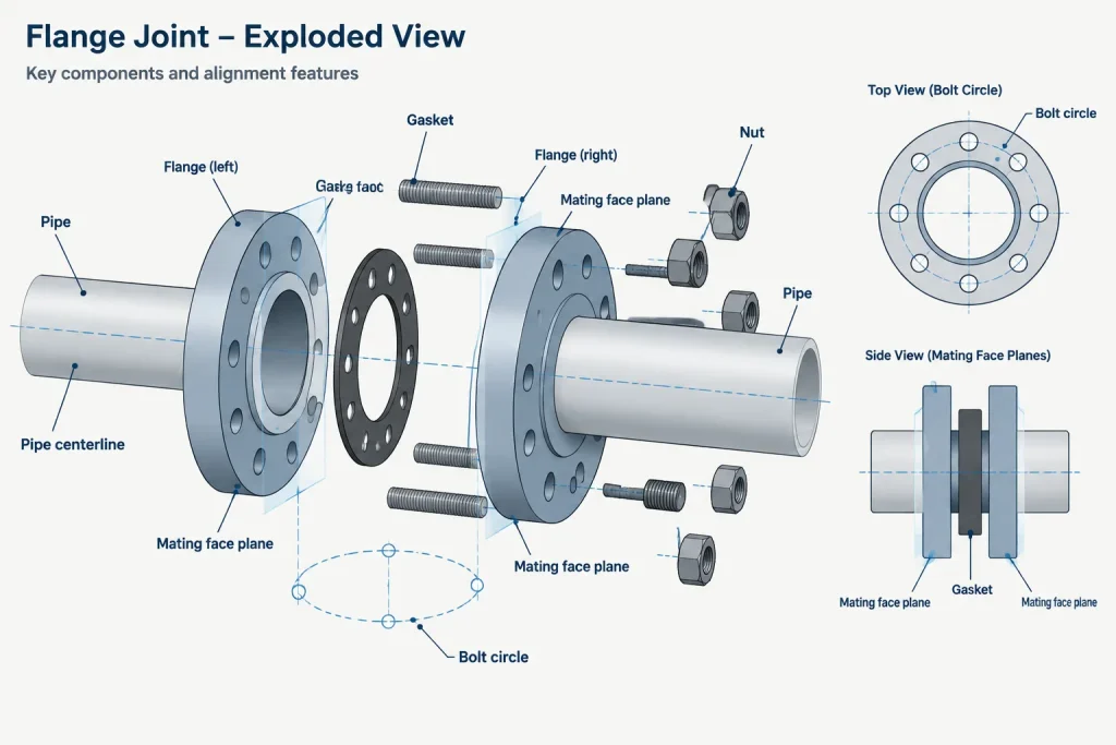
Two flanges with the same nominal size are not necessarily suitable mating components. A compatibility review normally considers several attributes together.
| Attribute | Why it matters |
|---|---|
| Nominal size | Identifies the piping size family but does not define the complete joint. |
| Dimensional standard | Controls the applicable flange geometry and bolting arrangement. |
| Pressure class or rating designation | Affects dimensions and the conditions under which the component may be used. |
| Facing | Must suit the gasket arrangement and opposing joint face. |
| Bolt pattern | Hole count, hole size, and bolt circle must align. |
| Material and specification | Must meet the piping material class and service requirements. |
| Bore or end preparation | Must suit the connected pipe and attachment method. |
| Flange type | Determines how the flange connects to pipe and affects fabrication geometry. |
A visual match in a CAD model does not prove that these attributes agree. Simplified components may hide differences in bore, facing, hub profile, or bolt holes.
How Pressure Class Affects Flange Geometry
Pressure class is not another name for pipe schedule, and it is not simply a fixed pressure value. It identifies a flange rating family whose permitted pressure depends on factors including material and temperature.
Within a dimensional system, changing class can change flange thickness, outside diameter, hub dimensions, and bolting. The nominal pipe size may remain unchanged while the physical envelope becomes different.
This has practical layout consequences. A class change can affect:
- Clearance to nearby pipes, steel, and equipment
- Bolt and tool access
- Valve and fitting envelope dimensions
- Joint stack-up and stud length
- Insulation or removable-cover geometry
- Weight and support data
For this reason, changing a flange class in a component record should trigger a geometry and coordination review rather than a text-only revision.
Reducing Flanges Are a Special Case
A reducing flange connects a flange joint of one nominal size to a smaller piping bore or connection. Its description therefore needs more information than a single size value.
Depending on the project naming convention, the larger joint size and smaller connected size may both appear in the designation. The order must be defined consistently so that designers, buyers, and fabricators do not interpret the same entry differently.
Reducing flanges also demonstrate why the flange body size and bore size cannot always be inferred from each other. The joint envelope may correspond to the larger nominal flange size while the opening is configured for the smaller connection.
A Practical CAD Selection Workflow
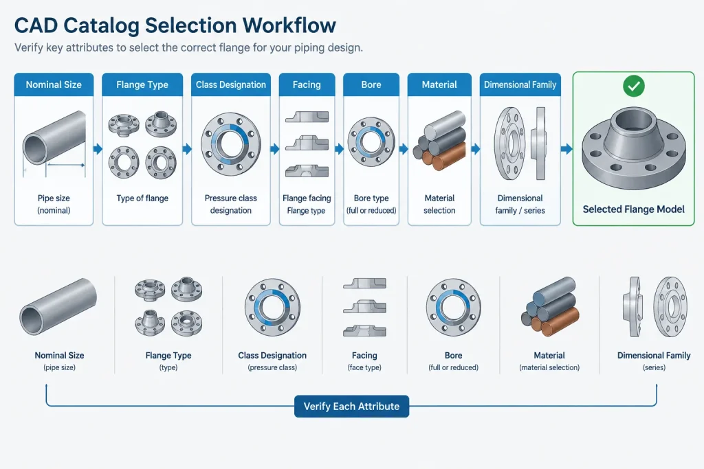
A controlled workflow separates line-size information from flange-specific data. Before placing or approving a flange component, verify the following:
- Read the piping class. Confirm the permitted flange type, material, facing, rating designation, and end connection.
- Identify the nominal line size. Do not derive it from a measured model diameter unless the component data is unavailable and the result will be independently verified.
- Confirm the dimensional family. Similar-looking flanges from different standards or product systems should not be assumed interchangeable.
- Select the correct flange class. Review both metadata and the resulting physical envelope.
- Check the facing. The face plane and facing type affect the gasketed joint and model connection point.
- Verify the bore or attachment geometry. This is especially important for weld neck, socket-weld, threaded, and reducing flanges.
- Review the bolt pattern and orientation. Confirm that mating components use compatible hole geometry and that bolt access is practical.
- Compare against vendor information where required. Standardized dimensions do not eliminate the need to verify proprietary equipment flanges or manufacturer-specific components.
Common Drafting and Modeling Errors
Labeling the Flange by Its Measured Outside Diameter
A measured flange outside diameter is a physical dimension, not the nominal pipe-size designation. Using it as the component size can lead to incorrect catalog searches and mismatched parts.
Assuming the Flange Bore Equals Pipe ID
Pipe inside diameter changes with wall thickness, while flange bore depends on flange type and component definition. The two dimensions may be related, but they are not interchangeable terms.
Changing Class Without Replacing Geometry
Editing a class field while retaining the old flange solid can leave the model envelope and bolt pattern inconsistent with the component description.
Using One Block for Every Flange Type
A schematic symbol may be acceptable on a P&ID, but a fabrication or detailed layout model often needs type-specific geometry. A weld neck flange, slip-on flange, blind flange, and socket-weld flange should not be treated as identical physical objects merely because they share a nominal size.
Assuming Equipment Nozzles Follow the Line-Pipe Catalog
Equipment nozzle interfaces must be checked against approved equipment information. The connected process line may have a familiar NPS or DN designation, but the nozzle facing, projection, bore, drilling, and rating still require verification.
What to Store in a Flange CAD Record
A useful flange library record should keep the nominal size separate from physical and specification attributes. Typical fields include:
- Nominal size designation
- Flange type
- Pressure class or applicable rating designation
- Dimensional standard or catalog basis
- Material specification
- Facing type
- Bore or pipe-wall association where applicable
- End preparation or attachment method
- Component code or catalog identifier
- Verified source status and revision information
These fields make component replacement safer and help prevent a model from relying only on visual appearance.
Key Takeaway
Flange size is primarily a nominal piping designation, not a measurement of the flange body or opening. The connected pipe OD, flange bore, flange outside diameter, bolt pattern, facing, class, and attachment geometry are separate characteristics.
For drafting and CAD work, select flanges from verified dimensional and specification data rather than scaling generic geometry or judging compatibility by nominal size alone. A complete flange definition must describe both the piping connection and the bolted-joint system.
Read Flange Information in the Correct Order
Flange identification becomes clearer when the information is separated into functional groups. Start with the nominal connection, then evaluate the bolted interface, the pipe attachment, and the physical envelope.
Nominal Connection
The nominal size places the component in a piping size family. It is the starting point for selection, not a complete dimensional description.
Bolted-Joint Interface
The dimensional basis, class or rating designation, facing, bolt circle, hole arrangement, and gasket interface determine whether the joint faces can be assembled as intended. Matching bolt holes is only one part of this review.
Pipe-Side Attachment
The flange type determines how the pipe connects to the component. Bore, socket, thread, hub, and end-preparation information must be interpreted according to that attachment method rather than treated as interchangeable opening dimensions.
Physical Envelope
Outside diameter, thickness, hub profile, and bolting space affect layout clearance and access. These dimensions matter even when the nominal line size remains unchanged.
How to Interpret a Flange Callout on a Drawing
A reliable callout should identify enough attributes to distinguish the intended component from other flanges in the same nominal size family. If a drawing shows only nominal size, the flange definition may still depend on the piping class, line specification, equipment data, or an associated component schedule.
When reviewing a callout, ask whether it resolves the following:
- The nominal piping connection
- The flange type and pipe attachment method
- The applicable dimensional or catalog basis
- The class or rating designation
- The facing and gasket interface
- The required bore or wall association
- The material and component specification
If any required attribute is missing, do not infer it solely from visible geometry. Confirm it through the controlling project or vendor information.
Measurement Is a Check, Not a Complete Identification Method
Field measurements or dimensions taken from an imported model can help compare a component with verified reference data. They do not independently establish material, rating, facing details, dimensional basis, or suitability for service.
This distinction is especially important when a model uses simplified bolt holes, omits a raised or recessed face, suppresses internal geometry, or represents a manufacturer-specific interface. Treat measured geometry as evidence to be checked against controlled documentation rather than as the complete flange specification.
Frequently Asked Questions
Is flange size the same as flange outside diameter?
No. Flange size normally refers to the nominal piping connection. Outside diameter is a separate physical dimension governed by the flange design and dimensional basis.
Does flange bore equal pipe inside diameter?
Not as a general rule. Pipe inside diameter depends on wall thickness, while flange bore depends on flange type, attachment method, and component definition.
Can flanges mate if their bolt holes align?
Bolt-hole alignment alone does not establish compatibility. Nominal size, dimensional family, facing, rating designation, gasket arrangement, materials, bore, and project requirements must also be reviewed.
Does changing pipe schedule change flange outside diameter?
Pipe schedule concerns pipe wall thickness. Flange outside dimensions are controlled separately. However, pipe wall selection can affect bore or end-preparation requirements for flange types that connect directly to the pipe wall.
Why does a blind flange have a nominal pipe size?
The nominal designation identifies the flange joint that the blind closes. It does not imply that the blind flange contains a flow opening.
Can a flange be identified from a CAD model alone?
Not reliably in every case. Simplified models may omit facing, bore, threads, sockets, or other distinguishing details. Component metadata and verified project or manufacturer information should be checked with the geometry.