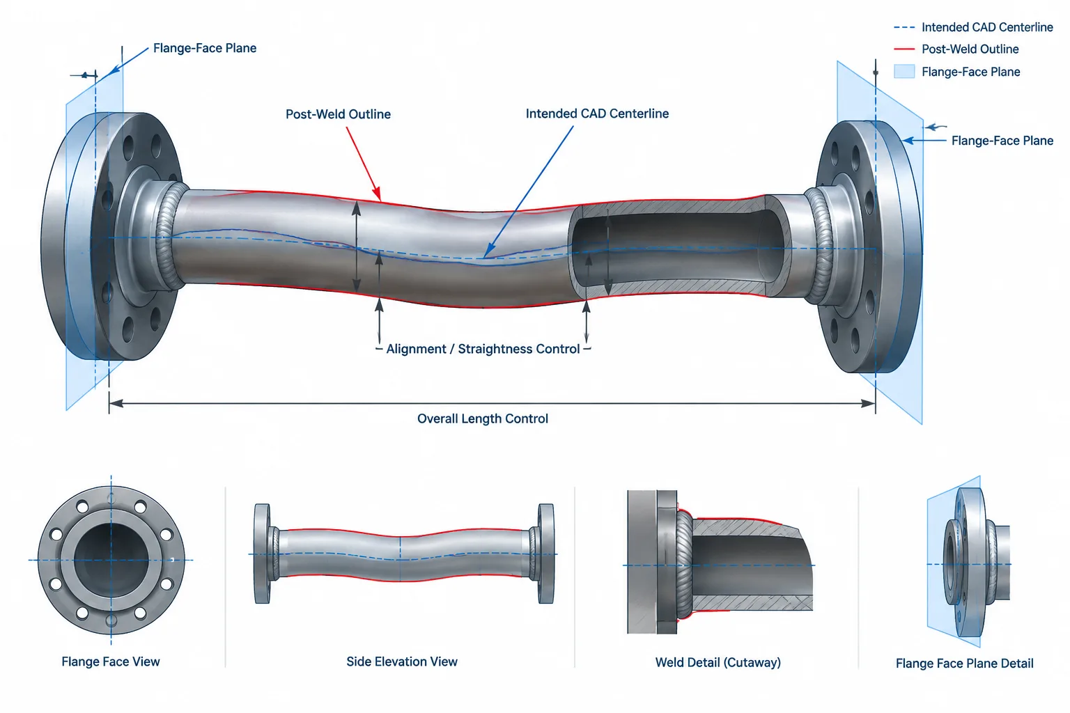
Weld shrinkage in piping fabrication is a production-control issue as well as a dimensional concern. A precise CAD model defines the required finished spool, but it cannot predict every movement caused by joint preparation, heat input, welding sequence, restraint, and fit-up.
This guide explains why nominal CAD cut lengths should remain distinguishable from shop-adjusted cuts, presets, and other fabrication compensation. It also outlines how designers, fabricators, and inspectors can preserve the intended connection geometry without embedding undocumented allowances in the model.
A piping spool can be modeled with exact coordinates and still change dimension during fabrication. One reason is weld shrinkage: the localized dimensional change that occurs as deposited weld metal and the surrounding heated base material cool. The resulting movement may be small, but several joints, restrained assemblies, or alignment-sensitive connections can make its effect important.
Weld shrinkage should not be handled by applying an arbitrary deduction to every CAD cut length. Its magnitude and direction depend on the joint, material, welding process, heat input, sequence, restraint, fit-up, and shop practice. The practical goal is to distinguish design geometry from fabrication compensation and assign control of each to the appropriate workflow.
What weld shrinkage means in piping fabrication
Welding introduces concentrated heat into a joint. Heated metal expands, while cooling weld metal and adjacent base material contract. Because this heating and cooling are not uniform throughout the assembly, the finished spool can experience dimensional change or distortion.
In piping work, weld-related movement may appear as:
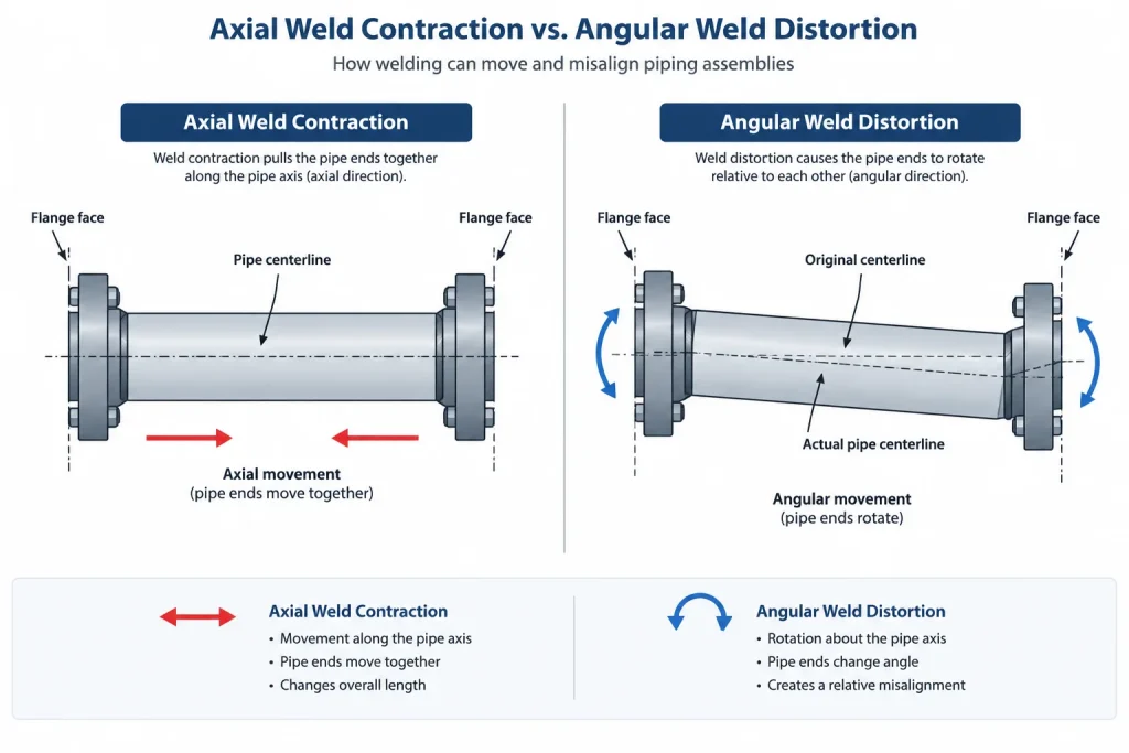
- A reduction or change in the overall length of a spool
- Angular movement at an elbow, branch, or mitered assembly
- Rotation or tilt of a flange face
- Loss of parallelism between two connection faces
- Branch movement away from its intended coordinate
- Accumulated error across several welded joints
These effects are related but not identical. Axial contraction changes length, while angular distortion changes orientation. A spool may have an acceptable overall length yet still fail a flange-alignment check because one face is tilted or rotated.
Why there is no universal shrinkage allowance
A single allowance cannot represent every piping weld. Even apparently similar joints may respond differently because their fabrication conditions differ. Relevant variables include:
- Joint geometry: Butt welds, branch welds, socket welds, attachment welds, and fabricated fittings heat the assembly differently.
- Wall thickness and component mass: The thermal response of a joint depends partly on the amount and distribution of material around it.
- Material: Different piping materials expand, conduct heat, and respond to welding in different ways.
- Welding process and procedure: Heat input, bead placement, pass sequence, and other qualified procedure variables affect the result.
- Fit-up: Root opening, alignment, tack welding, and joint preparation influence how the parts move during welding.
- Restraint: Fixtures may limit movement during welding, but releasing the fixture can allow residual distortion to appear.
- Weld sequence: The order in which joints and passes are completed can balance or compound movement.
- Assembly geometry: A straight spool behaves differently from an offset, branch assembly, or spool with multiple flanges.
For these reasons, compensation should come from an approved fabrication method, demonstrated shop history, controlled trial work, or project-specific instruction. It should not be invented by a CAD designer merely because the model is dimensionally exact.
Design dimensions and fabrication compensation are different data
The CAD model normally represents the required finished geometry: pipe centerlines, fitting locations, flange faces, equipment interfaces, and connection coordinates. Fabrication compensation is a production adjustment intended to achieve that finished geometry after welding.
Keeping those concepts separate prevents a common problem: modifying the design model so that it depicts a deliberately pre-adjusted shop assembly without clearly identifying the change. If another user later measures the model, extracts an isometric, or replaces a component, the adjusted geometry may be mistaken for the actual design requirement.
| Information | Typical purpose | Preferred control |
|---|---|---|
| Finished flange-face location | Defines the required installed interface | Design model and issued drawing |
| Pipe centerline and fitting location | Defines routing and finished spool geometry | Design model |
| Nominal pipe cut length | Supports material preparation and fabrication planning | Controlled cut list or fabrication output |
| Weld shrinkage compensation | Offsets expected fabrication movement | Shop procedure or approved fabrication instruction |
| As-built measurement | Records the completed condition | Inspection or survey record |
A project may organize these records differently, but the distinction should remain visible. Finished design dimensions should not silently become pre-weld dimensions.
How shrinkage can affect pipe cut lengths
A theoretical pipe cut length is commonly derived from the required finished geometry and the dimensional takeout of adjoining components. That calculation establishes the nominal relationship among the parts. It does not automatically account for every fabrication effect.
If compensation is required, a shop may adjust a cut piece, preset an angle, control the assembly in a fixture, or use a planned welding sequence. The chosen method depends on fabrication practice. Adding material to every cut piece is not necessarily correct, because weld movement may be angular, restrained, distributed among several joints, or corrected by another assembly method.
Cut lists should therefore identify their basis. A list may contain nominal design cuts, shop-adjusted cuts, or released fabrication cuts. Users need to know which one they are reading. Revision control is especially important if the shop changes a cut length after reviewing weld sequence or fit-up strategy.
Flanges and equipment connections need special attention
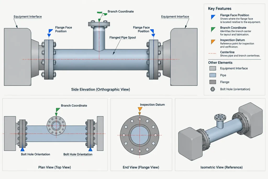
Flange interfaces are sensitive to more than spool length. The face may need to meet a required coordinate, orientation, parallelism condition, and bolt-hole clocking arrangement. Weld distortion at a flange neck or nearby fitting can affect several of these conditions at once.
When a spool connects between fixed equipment nozzles, there may be little freedom to absorb dimensional error. For these assemblies, the workflow may need verified interface measurements, suitable fabrication datums, controlled weld sequencing, intermediate checks, and final inspection before release.
The CAD model should clearly define the intended connection planes and coordinates. It should not imply that field bolting can be used to force a distorted spool into place. Pulling misaligned connections together can transfer unintended loads to flanges, nozzles, valves, or supports.
A practical CAD-to-shop workflow
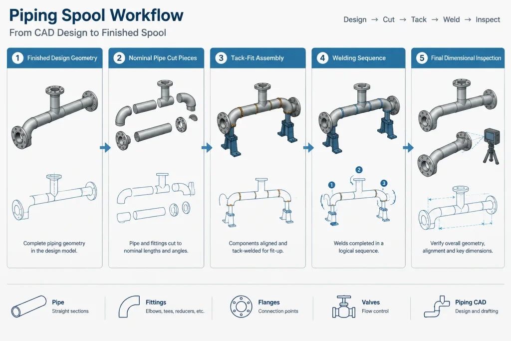
1. Establish the finished geometry
Model the required installed condition using controlled centerlines, component dimensions, flange-face planes, and interface coordinates. Resolve open design issues before relying on extracted cut lengths.
2. Identify alignment-sensitive spools
Flag assemblies connecting fixed nozzles, multiple flanges, close-tolerance interfaces, branches with critical coordinates, or other geometry that is difficult to correct in the field.
3. Extract nominal fabrication information
Generate cut lengths and spool dimensions from verified component geometry. State whether dimensions refer to faces, ends, centerlines, or other datums. Avoid mixing overall and chained dimensions without a clear hierarchy.
4. Apply compensation through a controlled method
If fabrication compensation is needed, it should be applied under shop or project procedures. Record whether the change affects a raw cut, fit-up position, preset angle, fixture arrangement, or weld sequence.
5. Inspect during assembly
Checking only after all welds are complete may reveal a problem too late for easy correction. Intermediate checks can monitor face position, angularity, branch location, and overall spool geometry as fabrication progresses.
6. Record departures from nominal data
If the shop changes a released cut or preset condition, preserve the change in the appropriate fabrication record. Update the design model only when the finished design condition itself changes or when the project requires verified as-built information to be incorporated.
Common documentation mistakes
- Using a blanket allowance: Applying one adjustment to every weld ignores joint type, sequence, restraint, and assembly geometry.
- Hiding compensation in the model: Moving a flange or fitting without annotation corrupts the finished design geometry.
- Confusing cut length with final spool length: Component takeout, joint arrangement, and fabrication effects separate these measurements.
- Checking only one dimension: Overall length alone does not verify flange tilt, branch position, or bolt-hole orientation.
- Accumulating assumptions: Several independently adjusted joints can create a larger dimensional error across the spool.
- Ignoring the fabrication datum: Measurements taken from inconsistent ends or centerlines can make good work appear incorrect.
What drawings should communicate
Fabrication drawings should define the required finished condition and the datums needed to verify it. Depending on the spool, useful controls may include flange-face-to-face dimensions, centerline coordinates, branch locations, face orientation, bolt-hole clocking, and references to the applicable fabrication instructions.
Notes should not prescribe an unverified shrinkage value. If compensation is controlled by a separate shop procedure, the drawing can reference that workflow according to the project document system without attempting to reproduce procedure details.
It is also helpful to distinguish inspection dimensions from informational dimensions. A small set of clearly prioritized controls is often more useful than a dense chain of dimensions that can conflict after rounding, revision, or component replacement.
The key principle
CAD should define where the finished piping must be; fabrication planning should define how the assembly will arrive there. Weld shrinkage sits between those two activities. Treating it as a controlled production variable—rather than a universal drafting deduction—helps preserve model integrity, improve spool inspection, and reduce alignment problems at installation.
How to review a shrinkage-related dimensional problem
When a completed spool does not match its intended geometry, the review should separate design data, fabrication instructions, and inspection results. This helps determine whether the issue originated in the model, the cut information, fit-up, welding, measurement, or document control.
- Confirm the governing geometry: Identify the released flange faces, centerlines, branch coordinates, and other finished-condition datums.
- Verify the cut-length basis: Determine whether the recorded value was nominal, shop adjusted, or revised after fit-up planning.
- Review the complete assembly: Check orientation and angular movement rather than treating overall length as the only acceptance concern.
- Compare fabrication records: Look for documented presets, fixture use, weld sequencing, intermediate measurements, and approved shop changes.
- Confirm the measurement datum: Ensure that design, shop, and inspection measurements reference the same faces, ends, centerlines, or connection planes.
- Protect model integrity: Do not revise the design geometry merely to make it agree with an undocumented pre-weld condition.
Responsibility at the CAD-to-shop handoff
The design team should communicate the required finished interfaces and the dimensional basis used to derive nominal cuts. The fabrication team should control any compensation needed to achieve those interfaces using its approved methods. Inspection should then verify the completed spool against the required finished condition.
Clear ownership does not eliminate coordination. Alignment-sensitive assemblies benefit from early review among drafting, fabrication, welding, and inspection personnel. The objective is not to make CAD predict every thermal response, but to ensure that design intent and shop action remain traceable.
Frequently asked questions
Should weld shrinkage be deducted from every CAD pipe cut length?
No. A blanket deduction does not account for joint geometry, material, process, sequence, restraint, fit-up, or assembly configuration. Any compensation should follow an approved fabrication method or demonstrated shop practice.
Does an exact CAD model guarantee that a fabricated spool will fit?
No. CAD precision defines the intended geometry, while fabrication introduces variables such as welding movement, fit-up conditions, restraint, and measurement practice. Shop control and inspection are still necessary.
Should compensation be modeled by moving fittings or flange faces?
Not unless the finished design condition itself has changed or the project specifically requires a controlled fabrication representation. Hidden geometry changes can cause later users to misread the intended interface.
Is overall spool length enough to check weld shrinkage?
No. A spool can meet an overall length while still having flange tilt, rotation, loss of parallelism, or branch displacement. Inspection should address the geometry that matters at each connection.
Who should establish a shrinkage allowance?
Compensation should be established through the applicable shop or project workflow, supported by approved procedures, fabrication experience, controlled trials, or project-specific instruction. It should not be an arbitrary drafting assumption.
What should a cut list say about adjusted lengths?
It should clearly identify whether values are nominal design cuts, shop-adjusted cuts, or released fabrication cuts. Changes should remain under revision control so users understand the basis of the information.