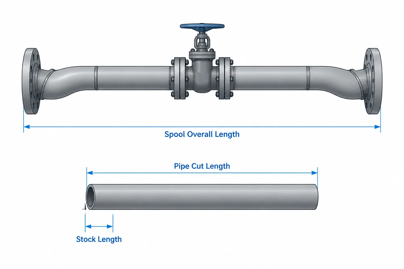
Pipe length terminology connects design geometry with purchasing, cutting, assembly, inspection, and installation. Although several documents may show a value called “length,” each value can use different endpoints, reference paths, and component boundaries.
This guide explains how stock length, cut length, developed length, and spool overall length fit into a practical piping workflow. It also shows why the intended measurement reference must be identified before a CAD dimension is transferred to a material takeoff, cut list, or fabrication drawing.
A dimension labeled “length” can refer to several different things in piping work. It may describe the pipe received from a supplier, a piece cut in the shop, the centerline path through a bend, or the overall distance between the ends of an assembled spool. These values are related, but they are not interchangeable.
Clear pipe length terminology helps prevent purchasing errors, incorrect cut lists, duplicated fitting allowances, and disagreement between CAD models and fabrication drawings. The essential question is not simply how long is it? It is which reference points, component boundaries, and fabrication conditions define that length?
Why “Pipe Length” Is Ambiguous
A piping model commonly represents a connected system rather than a collection of isolated raw pieces. A straight model segment may run between fitting connection points, while the physical pipe inserted between those fittings is shorter. Conversely, the overall spool dimension includes fittings, flanges, valves, or other components in addition to straight pipe.
Different project groups also use length for different purposes:
- Procurement needs quantities and available supply lengths.
- Material control needs to know how many cut pieces can be obtained from stock.
- Fabrication needs actual pipe cut lengths and end preparations.
- Layout controls centerlines, elevations, equipment interfaces, and overall geometry.
- Inspection needs identifiable measurement points on the finished assembly.
A useful drawing, model, or data export should therefore identify the type of length instead of relying on the word “length” alone.
Common Pipe Length Terms
| Term | What it generally describes | Typical use |
|---|---|---|
| Stock or supply length | A commercial piece of pipe before project-specific cutting | Purchasing, receiving, nesting, and inventory |
| Cut length | The physical length of one straight pipe piece prepared for assembly | Shop cutting, piece marking, and cut lists |
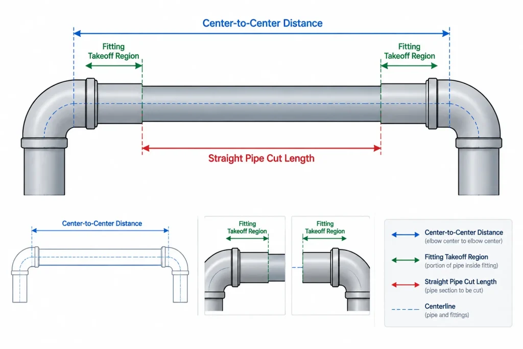
| Center-to-center length | The distance between component or routing center points | Layout and isometric dimensioning |
| Face-to-face or end-to-end length | The distance between defined external component faces or ends | Assembly control and interface checking |
| Developed length | The length measured along a defined path, commonly a centerline | Bends, offsets, and routed geometry |
| Tangent length | A straight distance measured to or between bend tangent points | Bend definition and fabrication |
| Spool overall length | The total extent of an assembled spool between stated endpoints | Fabrication inspection, shipping, and installation |
| Field-fit or trim length | A piece intentionally left for adjustment using verified field conditions | Tie-ins and closure work |
These descriptions are general workflow concepts. A project specification, fabricator procedure, purchasing document, or software system may use more specific labels, so the governing definition should be confirmed.
Stock Length Is Not a Fabrication Cut Length
Stock length describes the pipe available for cutting, not the finished length of a spool piece. Supply arrangements vary by material, product form, supplier, and purchase order. A designer should not assume that every material is delivered in one universal length or that the full nominal supply length is usable.
Material planning may need to account for damaged ends, identification retention, test coupons, saw kerf, end preparation, and remnants that are too short for another required piece. These are production controls rather than routing dimensions.
A material takeoff may total the required linear quantity of pipe, but that total alone does not provide a cutting plan. The shop still needs individual piece lengths and a nesting strategy for allocating those pieces to available stock.
Cut Length Applies to One Physical Pipe Piece
Cut length is the length of a straight pipe piece before or after specified end preparation, depending on the fabrication convention. That distinction matters. A plain-ended piece, a beveled piece, and a threaded piece may use different practical measurement references even when they occupy a similar part of the assembly.
The cut length should not be calculated by blindly copying the distance between component centers. The fitting portions occupying that distance must be considered. In a simple run between two elbows, for example, the straight pipe cut length is commonly derived from the controlled center-to-center distance after subtracting the applicable fitting takeoffs. The actual takeoff values must come from verified component dimensions.
Connection type also changes the calculation. Butt-weld, socket-weld, threaded, grooved, and flanged assemblies do not share one generic insertion or end-reference rule. A cut list should preserve enough connection information for the calculation to be checked.
Define the Pipe End Reference
A cut-length dimension is incomplete if the pipe ends are not clearly defined. Possible references include:
- physical square-cut ends;
- bevel toes, bevel reference planes, or other specified preparation points;
- ends before threading or machining;
- ends after final preparation;
- field-cut lines; or
- theoretical intersection points used for layout.
The appropriate reference depends on the fabrication process. CAD geometry should not silently substitute a convenient model endpoint for the shop’s required measuring point.
Developed Length Follows a Path
Developed length is a path-based value rather than a direct endpoint distance. For a straight piece, the developed length and direct length may coincide. For a bend or a routed shape, they generally do not.
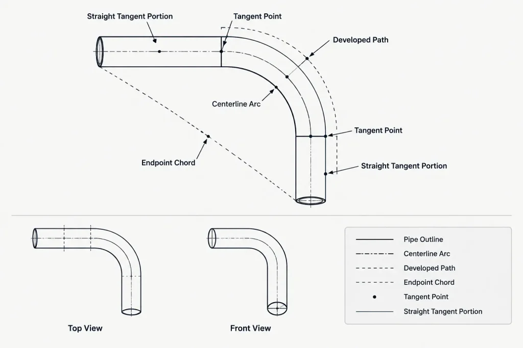
A bent pipe can be described by its centerline path, tangent points, bend radius, bend angle, and straight tangent portions. The developed length typically combines the relevant straight portions with the arc length along the defined reference path. It should not be confused with the chord, which is the straight-line distance between two points on the curve.
The reference path must be stated. A centerline developed length differs from a length measured along the inside or outside surface of a bend. Fabrication methods may also require allowances that cannot be inferred from ideal CAD geometry alone.
Tangent Dimensions Define Where Curvature Starts and Ends
A tangent point marks the transition between a straight run and a curved bend. Tangent-to-tangent dimensions are useful when the bend is fabricated from pipe because they separate straight portions from curved geometry.
This terminology is especially important when a drawing contains both pipe bends and manufactured elbows. A bend is often controlled through radius, angle, and tangent geometry. A fitting elbow is normally placed using verified fitting dimensions and connection points. Treating both as identical centerline arcs can produce an incorrect cut list or bill of material.
Spool Overall Length Includes More Than Straight Pipe
Spool overall length describes an assembled extent between identified endpoints. Those endpoints might be flange faces, pipe ends, weld-preparation planes, fitting ends, or another project-defined interface. The value can include several pipe pieces and components.
For example, the overall length of a flanged spool may include the flange projections and the straight pipe between them. It is not the same as the pipe cut length. Likewise, a spool containing an elbow may have an overall envelope that differs in each coordinate direction, so one dimension cannot fully describe it.
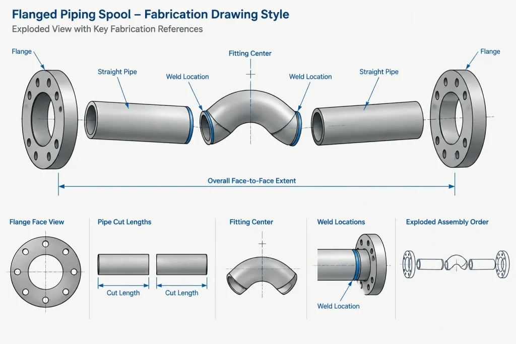
Overall dimensions are valuable for inspection and installation only when they use accessible, repeatable measurement points. A theoretical fitting center may help control layout but may be difficult to measure on a finished assembly. Fabrication drawings often need both layout dimensions and practical check dimensions.
Field-Fit and Trim Lengths Require Special Control
A field-fit piece is intentionally not finalized solely from design-model geometry. It provides a controlled way to accommodate an existing-system interface or another condition that must be verified in the field.
The drawing should distinguish the fixed portion from the adjustable portion and explain which end is to be trimmed. It should also identify the field measurement or interface controlling the final cut. A field-fit designation is not permission to leave the whole spool undefined.
Designers should avoid presenting a provisional cut length as a final shop dimension. Status, hold points, and field-verification requirements should remain visible in the model data, isometric, and fabrication package.
A Practical CAD and Drawing Workflow
- Establish layout references. Control equipment faces, nozzle locations, pipe centerlines, elevations, and tie-in points.
- Use verified component geometry. Confirm fitting takeoffs, flange dimensions, valve lengths, and connection details from approved project sources.
- Separate routing dimensions from fabrication dimensions. Center-to-center routing geometry should not automatically become a cut length.
- Define end conditions. Record whether each pipe end is plain, beveled, threaded, socket inserted, grooved, or field trimmed.
- Calculate individual pipe pieces. Derive cut lengths using the correct component boundaries and connection rules.
- Check spool extents independently. Compare face-to-face, end-to-end, and coordinate dimensions against the intended interfaces.
- Flag nonfinal values. Clearly identify field-fit pieces, vendor-dependent dimensions, and unresolved interfaces.
- Coordinate outputs. Confirm that the model, isometric, cut list, bill of material, and spool drawing use consistent identifiers and revision status.
Common Length-Control Mistakes
- Using total pipe quantity as though it were a list of cut pieces.
- Calling a center-to-center dimension a cut length without subtracting fitting takeoffs.
- Including a fitting allowance twice because both the CAD component and manual calculation account for it.
- Measuring a bend by chord length instead of the required developed path.
- Dimensioning an overall spool to undefined or inaccessible reference points.
- Assuming a nominal stock length is the exact usable length received.
- Ignoring the effect of end preparation or connection engagement.
- Releasing field-fit geometry as though it were fully verified fabrication geometry.
Use Explicit Labels Instead of a Generic Length Field
The most reliable approach is to name the quantity being controlled: pipe cut length, center-to-center distance, tangent-to-tangent distance, developed centerline length, flange-face overall length, or field trim allowance. Explicit labels make calculations reviewable and help downstream users understand whether a value belongs to routing, purchasing, fabrication, inspection, or installation.
A geometrically precise CAD model does not by itself settle every length question. Accurate piping documentation depends on verified component dimensions, clear reference planes, defined end conditions, and consistent terminology across all deliverables.
How to Review a Pipe Length Before Release
Before approving a length value, identify the object being measured and the task that the value supports. A procurement quantity describes material demand, while a fabrication dimension controls a physical piece or assembly. Using one value for both purposes without checking its definition can transfer a routing assumption into the shop.
- Identify the measured object: Determine whether the value applies to raw stock, one pipe piece, a bend path, a component, or a complete spool.
- Confirm the endpoints: Establish whether measurement begins and ends at pipe ends, connection planes, tangent points, component centers, or external faces.
- Confirm the path: State whether the value follows a centerline, a curved path, a coordinate direction, or a direct line between endpoints.
- Check component boundaries: Verify whether fittings, flanges, valves, and connection engagement are included or excluded.
- Check fabrication status: Distinguish theoretical model geometry from a released cut length, field-fit condition, or finished-spool inspection dimension.
- Use a specific label: Replace a generic length field with terminology that communicates the measurement basis.
Length Data Should Remain Traceable
A reliable workflow allows a reviewer to trace a finished-spool dimension back through component geometry, pipe-piece calculations, connection details, and layout references. This does not mean every deliverable must display every intermediate value. It means the calculation basis should remain available and consistent across the model, isometric, cut list, and inspection information.
When software generates lengths automatically, the output field name should be checked against the software’s actual measurement logic. A property called “length” may represent model geometry rather than the shop’s required cut reference. Automation improves consistency only when the property definition matches the intended fabrication use.
Frequently Asked Questions About Pipe Length Terminology
Is stock length the same as cut length?
No. Stock length describes material available before project-specific cutting. Cut length applies to an individual pipe piece prepared for assembly under a defined end-reference convention.
Can a center-to-center dimension be used directly as a pipe cut length?
Not automatically. Components occupy part of the center-to-center distance. The cut length must be derived using verified fitting geometry, connection details, and defined pipe-end references.
What is the difference between developed length and endpoint distance?
Developed length follows a specified path, commonly the pipe centerline through straight and curved portions. Endpoint distance is a direct measurement between stated points and does not represent the curved path.
Does spool overall length include fittings and flanges?
It can. Spool overall length covers the assembled extent between identified endpoints, so the included components depend on those endpoint definitions. The drawing should state whether the references are faces, pipe ends, preparation planes, or other interfaces.
Why should a drawing show both layout and check dimensions?
Layout dimensions control design geometry, but their theoretical reference points may not be accessible on a finished spool. Practical check dimensions give fabrication and inspection personnel repeatable physical measurement points.
How should field-fit pipe be represented?
The documentation should identify the fixed geometry, the adjustable portion, the end to be trimmed, and the field condition controlling the final cut. A provisional value should not appear to be a fully verified fabrication dimension.