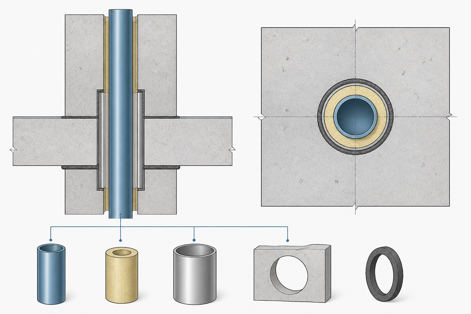
Pipe penetration details in CAD connect piping layouts with the actual wall, floor, roof, or equipment interface. A useful detail shows how the pipe relates to the opening and identifies the treatment required for construction, sealing, protection, and future coordination.
This guide is most useful when a drawing must communicate more than a pipe centerline. It explains how to organize penetration graphics, choose supporting views, coordinate discipline requirements, and maintain reliable tags through design revisions.
Why pipe penetration details matter
Pipe penetrations are small drawing features with large coordination consequences. A line that passes through a wall, floor, roof, or equipment enclosure must be represented in a way that communicates more than its centerline location. The drawing may need to show the opening, sleeve, seal, insulation, firestopping, waterproofing, and the relationship to the surrounding structure.
A clean penetration detail helps several disciplines work from the same information. Piping designers need to preserve routing and access. Structural designers need a defined opening or sleeve location. Architectural teams may need finished-surface information. Construction teams need to know whether the penetration is cast in, drilled, sleeved, sealed, or completed with a removable assembly.
This article explains a practical CAD workflow for detailing pipe penetrations. It does not replace project specifications, structural requirements, fire-resistance requirements, waterproofing details, or approved manufacturer instructions. Those documents determine the final construction arrangement.
Start by classifying the penetration
Before drawing geometry, identify what the pipe is passing through and what the penetration must accomplish. A penetration through a non-rated interior partition is not represented or reviewed in the same way as a pipe passing through a fire-rated wall, a tank enclosure, or a waterproofed roof.
| Penetration situation | CAD information commonly needed | Primary coordination concern |
|---|---|---|
| Wall or partition | Wall thickness, pipe location, sleeve or opening, seal arrangement | Clearance and wall construction |
| Floor or slab | Opening boundary, elevation, sleeve, curb or cover where applicable | Structural opening and trip or fall protection |
| Roof or waterproofed surface | Sleeve, curb, flashing, seal, and finished-surface relationship | Water exclusion and maintenance access |
| Fire-rated barrier | Penetration assembly, firestop identification, and rating reference | Approved firestopping system |
| Equipment enclosure | Connection location, removable access, and equipment boundary | Operation, maintenance, and equipment responsibility |
The classification should be recorded in the drawing notes, penetration schedule, or model properties. Avoid relying on a generic sleeve symbol to communicate all of these conditions.
Show the opening independently from the pipe
One of the most common drafting errors is drawing only the pipe crossing and leaving the opening implied. The pipe centerline identifies the route, but it does not define the construction interface. In plan, section, or elevation, show the wall, slab, or roof boundary and represent the penetration as a separate object.
Depending on the project standard, the opening may be shown as a sleeve, a formed opening, a core-drilled opening, or a framed opening. Use a distinct layer, block, hatch, or line type so the penetration remains visible when the pipe graphics are screened or hidden.
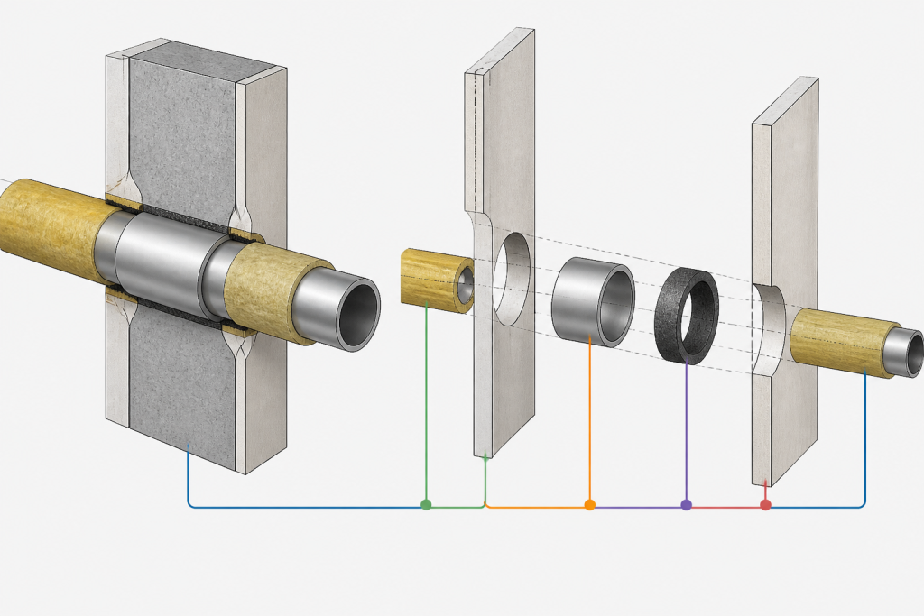
The detail should make the following relationships clear:
- The pipe axis or pipe outside boundary relative to the opening.
- The thickness and face locations of the penetrated construction.
- Whether the pipe is centered, offset, or intentionally close to one side.
- Whether insulation continues through the penetration or terminates before it.
- Where the seal, firestop, flashing, or cover is located.
Do not infer opening dimensions from a symbol unless the project drafting standard explicitly defines that symbol. Use the approved penetration schedule, structural opening data, or discipline-specific detail for the actual construction requirement.
Choose the right view for the information
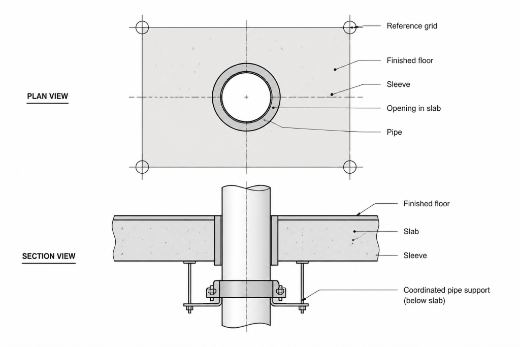
A plan view is useful for locating the penetration relative to grids, walls, equipment, and adjacent services. It may not show the sealing arrangement or vertical relationship to the slab. A section or elevation is usually needed when the penetration includes a sleeve, firestop, waterproofing, insulation termination, or a change in elevation.
Use multiple views when one view would force the reader to interpret hidden geometry. For example, a floor penetration may need a plan view showing the opening location and a section showing the sleeve, slab thickness, finished floor, and protection at the opening. Keep the views connected with a detail identifier or penetration tag.
Plan-view checks
- Confirm that the penetration is positioned from stable references such as structural grids, wall faces, column lines, or equipment datums.
- Check that nearby pipes, supports, cable trays, ducts, and access paths do not conflict with the opening.
- Show enough of the surrounding construction for the location to be verified in the field.
- Make sure the pipe symbol does not obscure the opening boundary or penetration tag.
Section-view checks
- Show the penetrated construction and the direction of the pipe through it.
- Identify sleeve, seal, firestop, flashing, curb, or cover components when they apply.
- Show insulation, cladding, or coating transitions rather than stopping them without explanation.
- Verify that supports and anchors do not transfer unintended loads to the wall, slab, sleeve, or equipment.
Coordinate sleeves, clearances, and insulation
A penetration opening must account for more than the nominal pipe size. The required construction space can be affected by insulation, external coating, pipe movement, installation tolerances, removable covers, and the selected sealing system. The correct value is project-specific and should come from the responsible design discipline, specification, or approved system detail.
In CAD, model or draw the pipe, insulation, sleeve, and opening as separate representations. This makes it possible to identify a common coordination mistake: a sleeve that appears adequate for bare pipe but conflicts with insulated pipe or a fitting near the wall.
Also check whether the pipe is intended to move relative to the penetration. Thermal expansion, vibration, settlement, and equipment movement can affect the interface. A rigidly drawn connection does not prove that the real installation can accommodate movement. Show a movement joint, flexible seal, guide, or other interface only when it is supported by the project design.
Handle firestopping and waterproofing as design information
Fire-rated and waterproofed penetrations require more than a generic note such as “seal around pipe.” The drawing should identify the required penetration treatment by a project detail, schedule reference, assembly designation, or specification note. The selected system may depend on pipe material, insulation type, opening construction, annular space, barrier rating, and installation orientation.
For roof and below-grade penetrations, distinguish the pipe sleeve from the waterproofing termination. A sleeve may provide a passage for the pipe, while flashing, membrane, sealant, or a curb provides water management. These functions should not be combined into an ambiguous symbol.
Where the final system is selected by another discipline or specialist, place a coordination note in the drawing and reference the responsible detail. Do not assign a fire rating, waterproofing performance, or tested assembly based only on a typical CAD block.
Use penetration tags and schedules consistently
A penetration schedule can reduce crowded notes and improve coordination between plans, sections, and construction documents. Give each penetration a unique identifier that remains stable through revisions. The identifier may connect the CAD location to information such as service, area, barrier type, sleeve or opening description, seal requirement, and responsible discipline.
| Schedule field | Purpose |
|---|---|
| Penetration ID | Connects the plan symbol, section detail, and schedule record. |
| Service or line reference | Identifies the pipe crossing the barrier. |
| Location | Provides room, grid, wall, floor, or equipment context. |
| Barrier type | Indicates wall, slab, roof, enclosure, or rated construction. |
| Treatment reference | Points to the approved sleeve, seal, firestop, or waterproofing detail. |
| Status | Shows whether the penetration is proposed, coordinated, approved, or field-verified. |
Keep tag text readable at the issued drawing scale. If a tag is moved for clarity, preserve its association with the actual penetration using a leader or consistent callout convention.
A practical CAD review workflow
- Extract the crossing locations. Review plans, elevations, sections, isometrics, and the coordinated model to identify every barrier crossing.
- Classify each condition. Separate ordinary openings from fire-rated, waterproofed, structural, or equipment-related penetrations.
- Confirm references. Check grids, wall faces, slab elevations, equipment datums, and pipe centerlines.
- Separate graphics. Use distinct objects or layers for the pipe, insulation, sleeve, opening, seal, and surrounding construction.
- Assign the penetration detail. Link the tag to the applicable approved detail or schedule record.
- Run a multidisciplinary review. Include piping, structural, architectural, fire protection, insulation, and construction stakeholders as applicable.
- Verify revisions. When routing changes, recheck the opening location, detail type, schedule entry, and all dependent views.
Common drafting mistakes to avoid
- Showing a pipe crossing without showing the wall, slab, roof, or opening interface.
- Using one generic sleeve block for every service and barrier condition.
- Ignoring insulation, coatings, cladding, or removable access requirements.
- Placing a penetration too close to a structural edge or adjacent opening without coordination.
- Allowing a section detail and plan location to carry different penetration identifiers.
- Assigning firestop or waterproofing performance without an approved project reference.
- Failing to update penetration schedules after a routing revision.
Final review checklist
Before issuing a drawing, confirm that each penetration has a verifiable location, an understandable representation, and a clear treatment reference. The pipe route should agree across plan, section, elevation, isometric, and model views. The opening should be coordinated with structure and nearby services. Insulation and support interfaces should be resolved, and any firestopping or waterproofing requirement should point to approved project information.
Good penetration detailing does not make assumptions disappear; it makes them visible. By separating the pipe from the opening and identifying the construction treatment, a CAD drawing becomes a useful coordination document rather than only a routing diagram.
How to use this CAD detailing guidance
Think of a penetration as a coordinated interface rather than a single drafting symbol. The pipe, surrounding construction, opening or sleeve, insulation, seal, and protective treatment may each have different design ownership. Separating these elements in the drawing helps reviewers identify what is known, what requires coordination, and which approved project detail governs the final installation.
What to verify during review
- Location: Confirm the penetration against stable architectural, structural, equipment, or piping references.
- Representation: Make the opening or sleeve visible independently from the pipe graphics.
- Interface: Check insulation, coatings, supports, movement, access, and nearby services.
- Treatment: Reference the applicable firestop, waterproofing, sealing, or construction detail instead of relying on an unexplained typical symbol.
- Documentation: Keep plan callouts, sections, schedules, model properties, and revision information aligned.
The existing technical guidance below provides the detailed workflow and review considerations. Use it alongside project specifications, structural coordination, fire protection requirements, waterproofing information, and approved manufacturer or system documentation.
Frequently asked questions
Why should the opening be shown separately from the pipe?
The pipe indicates routing, but it does not define the construction interface. Showing the opening or sleeve separately communicates the relationship between the pipe and the wall, slab, roof, or enclosure and makes coordination easier.
When is a section view needed for a pipe penetration?
A section is useful when the penetration includes a sleeve, seal, firestop, waterproofing, insulation transition, elevation change, cover, or other vertical relationship that a plan view cannot explain clearly.
Can one generic CAD sleeve block be used for every penetration?
A generic symbol may be useful for preliminary coordination, but it should not replace classification and project-specific treatment information. Penetrations can differ by barrier type, service, insulation, movement, sealing system, and responsible discipline.
What should a penetration schedule identify?
A schedule commonly connects a stable penetration identifier with the service, location, barrier type, treatment reference, and coordination status. The exact fields should follow the project documentation standard.
Who approves firestopping and waterproofing details?
Approval depends on the project organization and the governing design responsibilities. The CAD drawing should reference the approved project detail, schedule, specification, or specialist information rather than assigning performance based on a typical block.
What should be checked after a pipe route changes?
Recheck the penetration location, opening or sleeve condition, supporting views, tag association, schedule record, nearby clearances, insulation interface, and any dependent structural, fire protection, architectural, or waterproofing information.