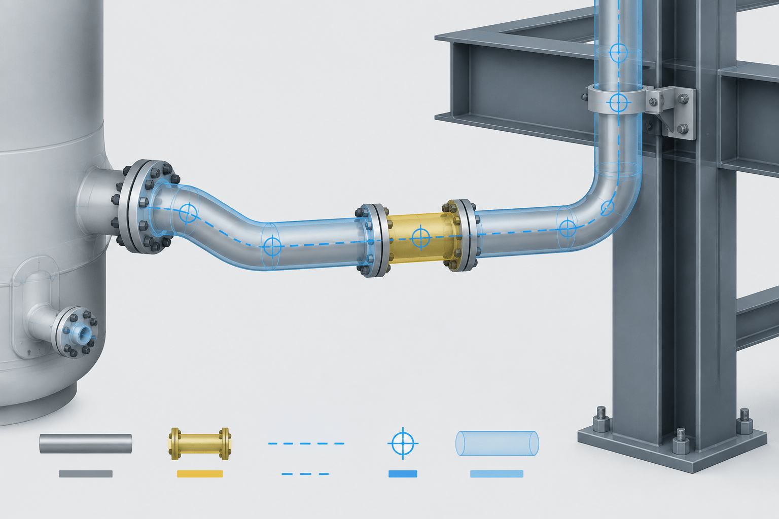
Piping CAD drawings must communicate a precise design intent while recognizing that fabrication, installation, equipment setting, and existing conditions can introduce variation. The practical challenge is not to make a model appear perfectly exact; it is to make the status of each interface understandable to everyone who relies on the drawings.
This guide explains how to distinguish nominal layout geometry from dimensions that require verification, fit-up planning, or coordination with other disciplines. It is particularly relevant when preparing routing models, isometrics, spool information, tie-in packages, and drawings that connect piping to equipment, structure, or existing plant systems.
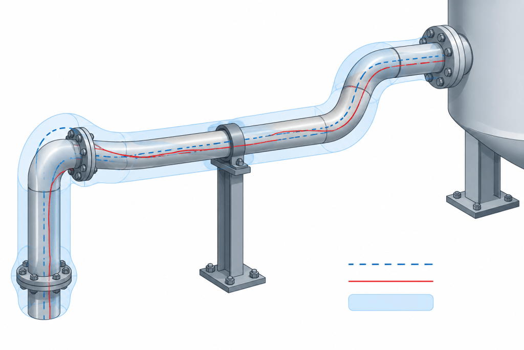
A piping CAD model must be precise enough to communicate design intent, support coordination, and produce usable drawings. That does not mean every displayed dimension represents an exact field condition. Fabricated pipe, fittings, supports, steelwork, equipment nozzles, and existing plant conditions all have permitted variation. A practical piping drawing distinguishes between nominal geometry—the intended arrangement—and the tolerances, adjustment locations, and verification steps needed to make that arrangement buildable.
This distinction matters because CAD can create an appearance of absolute certainty. A modeled centerline may meet a nozzle centerline exactly, a spool may appear to fit perfectly between flanges, and a support may align precisely with structural steel. In the field, each interface can vary. Good detailing does not hide that reality; it shows where the design is fixed, where adjustment is possible, and what must be confirmed before fabrication or installation.
What nominal geometry means in a piping model
Nominal geometry is the idealized layout used to establish routing and relationships. It commonly includes pipe centerlines, fitting centers, nozzle locations, flange faces, support locations, structural reference lines, and elevation control points. The model uses the selected component dimensions from the applicable project data and reference tables, but it remains an engineering representation rather than a direct measurement of every installed condition.
For example, a CAD model may show a pipe run centered between two steel members. That centerline is valuable because it establishes intended clearance, routing sequence, and branch location. It should not automatically be interpreted as a promise that every fabricated piece will arrive at the site with no dimensional variation or that the steel will be installed at precisely the model location.
Nominal geometry is especially useful for these tasks:
- Coordinating pipe routes with equipment, structure, cable trays, and accessways.
- Establishing piping elevations and slope direction.
- Locating branch connections, valves, instruments, and supports.
- Creating isometric dimensions and spool boundaries.
- Identifying maintenance removal paths and access envelopes.
- Checking that selected fittings and flanges are represented with the correct reference dimensions.
The model should be accurate to the project’s defined basis, but its users must understand which geometry is controlled by issued design information and which geometry still depends on field verification.
Why false precision creates problems
False precision occurs when a drawing presents a dimension as fixed even though the condition has not been surveyed, released by another discipline, or finalized by the responsible supplier. It can cause fabricators and installers to assume that an exact fit is required where the design actually needs adjustment capability.
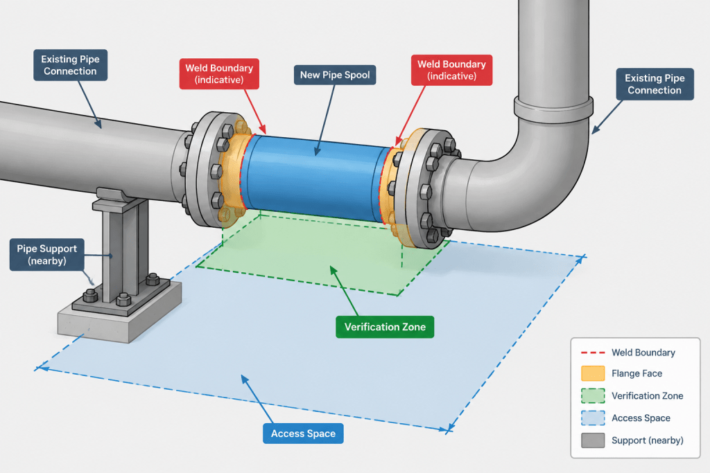
A common example is a final connection between new piping and an existing line. Modeling the connection as a complete, exact spool may make the drawing look finished. If the existing line location is based on legacy drawings rather than a current field measurement, however, the exact closure length is uncertain. Issuing that piece as a normal shop spool can lead to field rework, incorrect flange alignment, or an unnecessary dispute over who owns the discrepancy.
False precision can also appear at equipment interfaces. A vendor drawing may provide nozzle coordinates for layout, while final equipment setting, nozzle orientation, or flange projection remains subject to release and installation. The piping team should model to the best approved information available, but should not treat a preliminary interface as an immutable fabrication dimension.
Separate controlled dimensions from field-dependent dimensions
One of the most useful detailing habits is to classify dimensions by how they are controlled. This helps reviewers understand which dimensions can be fabricated directly and which need confirmation at a later stage.
| Dimension category | Typical basis | Drafting approach |
|---|---|---|
| Design-controlled | Approved layout, released equipment data, or established project coordinates | Show as primary dimensions or coordinates and identify the governing datum. |
| Fabrication-controlled | Spool geometry derived from approved pipe, fitting, and end-connection data | Dimension clearly on the spool or isometric, with weld and component references. |
| Field-verified | Existing piping, installed steel, final equipment position, or inaccessible site condition | Identify the connection as field verified and avoid implying that an unverified closure is final. |
| Adjustment-dependent | Planned fit-up location, field-routed segment, adjustable support, or removable connection | Show the intended adjustment strategy and preserve the responsible party’s ability to execute it. |
This classification does not replace project procedures, fabrication requirements, or survey practices. It makes the drawing more honest about the information available when the drawing is issued.
Use datums to make the layout verifiable
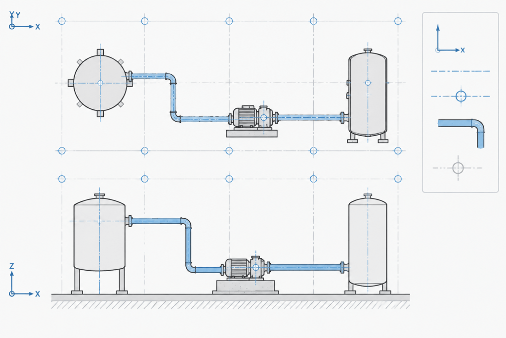
Tolerances are easier to manage when dimensions originate from stable, recognizable datums. A datum may be a plant grid intersection, a coordinate system, a finished floor elevation, an equipment centerline, a structural reference line, or another formally controlled point. The best datum is not simply the closest point on the drawing. It is the point that another person can locate consistently in the model, on site, and in related documents.
Dimension chains deserve particular attention. A long chain of dimensions can accumulate variation from multiple components and work activities. Where practical, critical interfaces should be located from a common control point rather than only from adjacent items. For instance, an equipment nozzle connection may be best coordinated from equipment centerlines and reference elevations, while an intermediate support can be dimensioned from the pipe centerline and nearby structure.
Good datum questions during review
- Can the installer identify this reference point in the field?
- Does the same datum appear consistently on the plan, elevation, section, and isometric?
- Is the dimension driven by a controlled coordinate, an assumed location, or a field measurement?
- Will a change to an upstream component shift several downstream dimensions?
- Is the drawing clear about which party must verify the interface?
Model adjustment locations deliberately
An adjustment location is not an omission in the design. It is a purposeful place where the installation can accommodate verified conditions within the project’s approved process. Depending on the system and project rules, this may involve a designated field weld, a closure spool, a field-routed segment, or another planned fit-up arrangement.
The key is to model and document the arrangement intentionally. A field adjustment point should not be confused with an ordinary shop weld or a missing pipe segment. On drawings, make its status understandable through the project’s established symbology, notes, weld identification practices, and spool boundaries. Coordinate it with inspection, testing, insulation, access, and support requirements as applicable.
When selecting a possible adjustment location, consider more than geometric convenience. A location that is easy to trim on paper may be difficult to access, impossible to inspect, too close to a valve, incompatible with insulation sequencing, or disruptive to a required slope. The piping designer should raise these constraints during coordination rather than assuming the field will solve them.
Account for tolerance-sensitive interfaces
Not all parts of a piping system react the same way to dimensional variation. Straight runs usually provide more layout flexibility than rigid interfaces. The following conditions deserve focused review:
- Equipment nozzles: Verify orientation, elevation, facing direction, connection type, and the status of vendor information.
- Flanged connections: Confirm that the modeled connection allows practical bolt-up, gasket installation, and alignment without forcing mating parts.
- Sloped piping: Protect the intended drainage or flow slope when deciding where a field adjustment can occur.
- Expansion-sensitive runs: Do not place an adjustment decision without considering anchors, guides, supports, and expected movement.
- Penetrations: Coordinate pipe envelope, insulation, sleeves, sealing details, and structural ownership rather than dimensioning only the bare pipe centerline.
- Existing-plant tie-ins: Treat record drawings and prior models as useful references, not substitutes for the project’s required field verification.
These are coordination principles, not a determination of suitability for any particular piping system. Final design and fabrication decisions must follow the governing project documents and responsible engineering review.
A CAD workflow for tolerance-aware detailing
- Establish the information status. Identify whether each interface is released, preliminary, existing, surveyed, or pending verification.
- Build nominal routing from controlled references. Use the project coordinate system and approved equipment or structural information.
- Identify rigid endpoints. Mark nozzle faces, tie-in points, penetrations, fixed supports, and other interfaces that constrain the run.
- Review closure paths. Look for segments that depend on multiple uncertain interfaces or that have no practical adjustment strategy.
- Define drawing ownership. State through standard project conventions whether a segment is shop fabricated, field fitted, or awaiting verification.
- Coordinate before release. Review the model with piping, structural, equipment, construction, and quality stakeholders as required by the project.
- Revise the model after verified information arrives. Preserve revision history so that superseded assumptions do not remain hidden in downstream drawings.
Keep reference tables and drawings in their proper roles
Pipe dimension and schedule tables provide the authoritative reference data needed to model nominal pipe geometry. Fitting and flange references support correct component representation. They are essential inputs, but they do not decide where fabrication variation can be absorbed or whether an existing installation matches its record information.
Use reference data to select and model the correct nominal components. Use coordinated drawings, surveys, vendor releases, project specifications, and construction feedback to manage real interfaces. Keeping these roles separate helps prevent a correct table lookup from being mistaken for a complete constructability decision.
Conclusion
Reliable piping drawings balance precision with transparency. Model the intended route accurately, dimension critical relationships from recognizable datums, and clearly identify interfaces that require verification or planned fit-up. The result is not a less exact drawing. It is a more useful one: a drawing that communicates what is fixed, what is nominal, and what must be resolved before the piping is fabricated and installed.
How to read this guide during drawing review
The central review question is simple: what information controls this location? A pipe centerline may be controlled by approved coordinates, a released equipment interface, a structural reference, or a field measurement. Identifying that basis helps the team decide whether the dimension can support shop fabrication, should remain subject to field confirmation, or needs a planned adjustment arrangement.
Nominal geometry remains essential even when an interface is not final. It allows routing, clearance review, support coordination, material planning, and multidisciplinary discussion to proceed using the best information available. The drawing becomes more reliable when it also makes uncertain interfaces visible rather than embedding assumptions in apparently final dimensions.
Useful relationships to check together
- Plan, elevation, and isometric: Confirm that the same controlling references and interface status are communicated across each drawing type.
- Model and vendor information: Verify whether equipment connection data is released for fabrication or retained for coordination only.
- Spool boundaries and field activities: Ensure the proposed fabrication split leaves a practical location for any required verification or fit-up work.
- Pipe routing and support intent: Review whether a field adjustment could affect support placement, accessibility, slope, or movement-related detailing.
- Existing-condition information and current survey records: Make clear when record information is being used as a reference rather than as final installation geometry.
Editorial takeaway
A tolerance-aware drawing does not reduce design accountability or transfer unresolved decisions to the installer. Instead, it records the intended arrangement, identifies the governing datums, and shows where approved project processes must resolve field-dependent conditions. This distinction supports clearer communication among designers, fabricators, construction teams, quality personnel, and owners.
Frequently asked questions
What is nominal geometry in piping CAD?
Nominal geometry is the intended modeled arrangement of pipe centerlines, components, interfaces, elevations, and related reference locations. It provides the design basis for coordination and detailing, but it may not represent the final measured position of every installed item.
Why should a piping drawing identify field-verified dimensions?
Field-verified identification prevents an unconfirmed condition from being interpreted as a final fabrication requirement. It helps the project team recognize that a measurement, survey, release, or fit-up activity is needed before the connection is finalized.
Is a closure spool the same as an incomplete design?
No. A closure spool or other planned adjustment location can be an intentional detailing strategy when an interface depends on verified installation conditions. Its purpose, fabrication status, and execution requirements should be communicated through the project’s approved drawing conventions.
Why are datums important for piping dimensions?
Datums provide common reference points that different teams can identify in the model, drawings, and field. Locating critical interfaces from stable datums reduces ambiguity and makes coordination changes easier to trace.
Can pipe reference tables determine fabrication tolerance or field fit-up requirements?
No. Reference tables support the correct representation of nominal pipe components and connections. Tolerance management, survey requirements, fabrication practices, and fit-up decisions depend on the applicable project documents, approved information, and responsible engineering review.