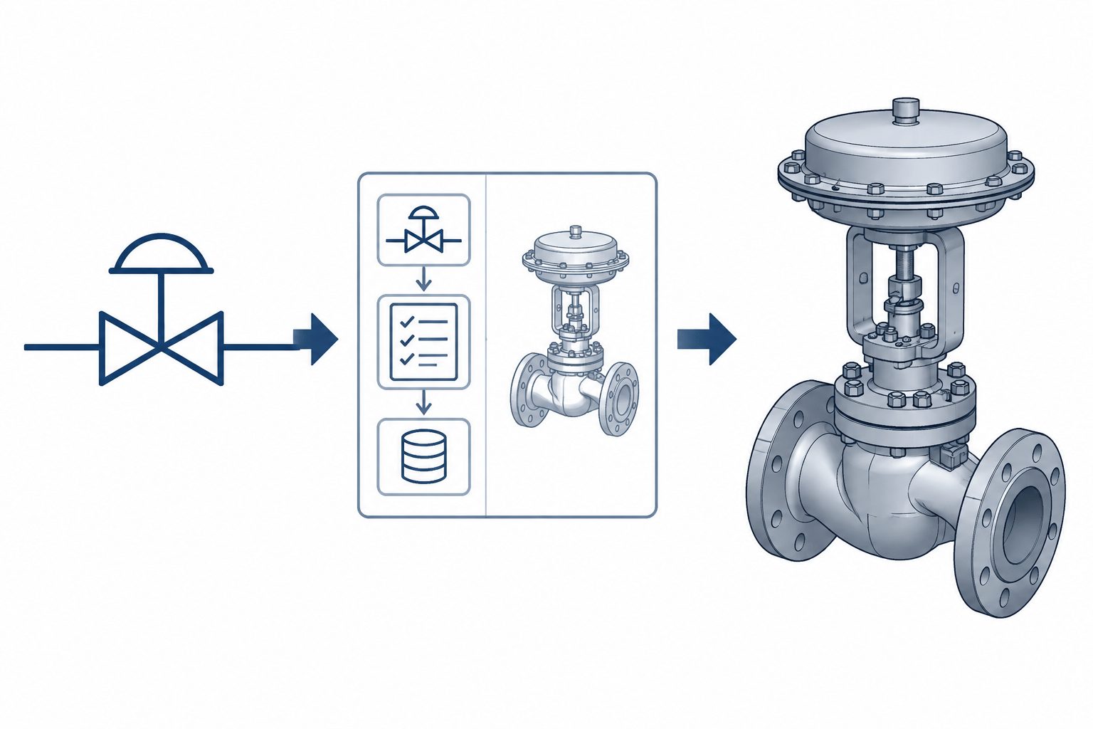
Translating P&ID symbols to 3D piping components is a document-control task as much as a CAD task. The diagram identifies process intent, but the physical model must combine that intent with piping specifications, line data, equipment interfaces, instrument requirements, and verified component information.
The objective is not to make the model resemble the schematic. It is to create a traceable physical representation in which component selection, connectivity, orientation, and model status can be checked against their controlling sources. The guidance below explains how to make that translation without treating an abstract symbol as dimensional evidence.
A piping and instrumentation diagram and a 3D piping model describe the same system from very different viewpoints. The P&ID communicates process function, connectivity, control intent, and equipment relationships. The 3D model defines physical components, routing, interfaces, access, and constructible geometry.
Problems occur when a designer treats a P&ID symbol as a miniature picture of the required hardware. Most symbols are intentionally abstract. They may identify a valve function without defining its body pattern, end connection, operator position, face-to-face dimension, or maintenance envelope. Translating the diagram into CAD therefore requires controlled interpretation rather than symbol tracing.
What a P&ID Symbol Usually Communicates
A P&ID symbol is primarily a functional identifier. Depending on the project drafting convention, the surrounding information may communicate:
- The general component type, such as a valve, strainer, reducer, instrument, or equipment item.
- The process connection between lines, branches, equipment, and instruments.
- A component tag or instrument identification.
- Normal operating position, fail action, or control relationship when explicitly noted.
- Line numbers and specification boundaries.
- Special functions such as check service, isolation, throttling, draining, venting, or pressure protection.
This information is essential, but it does not automatically define a purchasable component. A generic valve symbol, for example, may not establish whether the selected item is flanged, threaded, socket-welded, butt-welded, wafer-style, or supplied with another connection arrangement.
What the 3D Model Must Add
A physical CAD component needs more information than the diagram normally provides. The model may require defined connection ports, end preparation, nominal size, pressure class or other rating designation, dimensional standard, body geometry, operator arrangement, weight data, and access space. Some of these properties come from the piping material specification, while others come from project data sheets or vendor documents.
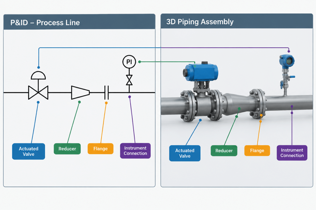
The translation should preserve the P&ID’s process intent while adding only verified physical information. If the exact component is not yet selected, the model should remain clearly preliminary rather than presenting assumed geometry as approved design data.
| Information | Typical controlling source | CAD use |
|---|---|---|
| Process function and connectivity | P&ID | Determines what must connect and the intended service relationship |
| Line size and line identification | P&ID and line list | Controls routing identity and nominal component size |
| Allowed material and component types | Piping material specification | Limits valid catalog selections |
| End connection and rating designation | Material specification, valve data sheet, or equipment document | Controls connection compatibility and component selection |
| Exact envelope and interface dimensions | Applicable dimensional reference or verified vendor data | Controls layout, replacement space, and adjoining pipe geometry |
| Operator, actuator, and accessory arrangement | Instrument data, valve data, and vendor documentation | Controls orientation, access, clearance, and support coordination |
| Insulation and maintenance requirements | Project specifications and discipline input | Controls physical clearance beyond the component body |
Common Translation Errors
Reading Symbol Shape as Body Shape
A schematic symbol should not be used to infer the exact outline of a valve, strainer, or instrument. Similar symbols may represent products with significantly different body envelopes. Conversely, physically different products may share a common schematic symbol because they perform the same process function.
Assuming an End Connection
A line touching a symbol does not necessarily identify how the real component joins the pipe. End connections must be checked against the material specification, component description, line class, and any associated data sheet. An incorrect assumption can change joint count, cut length, bolting, gasket requirements, and available maintenance space.
Ignoring Size Transitions Hidden by the Schematic
P&IDs are not normally drawn to scale. A valve, instrument, or equipment nozzle may be smaller than the main line even when the symbol appears directly in the line. The physical design may require reducers, branch fittings, flange transitions, or specialty connections that are not graphically obvious. Notes, instrument details, and equipment connection data must be reviewed before modeling.
Modeling the Operator in a Convenient Direction
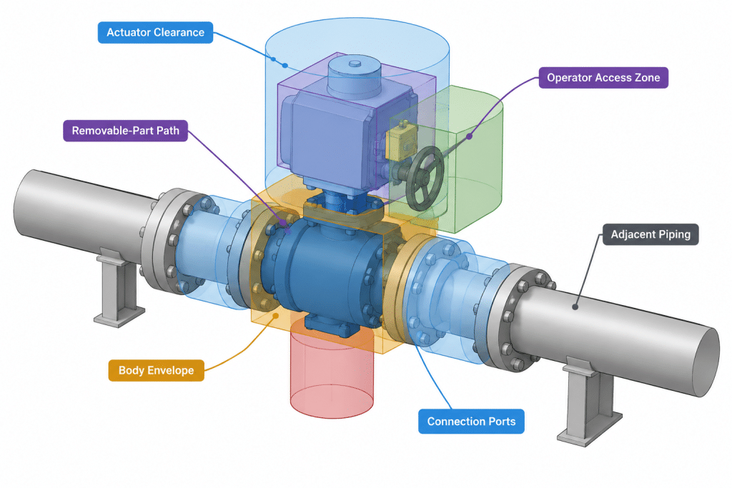
The P&ID may show a handwheel or actuator for identification without establishing its plant orientation. In 3D, operator direction affects access, platform layout, removal space, cable routing, tubing, and interference checks. Orientation should follow operating and maintenance requirements rather than the symbol’s page orientation.
Substituting a Generic Component Without Flagging It
Generic CAD geometry can be useful during early layout, but it should be identified as provisional when exact data are unavailable. Otherwise, downstream users may treat an approximate envelope or port location as verified. A placeholder should retain the correct tag and design intent while clearly indicating which properties still require confirmation.
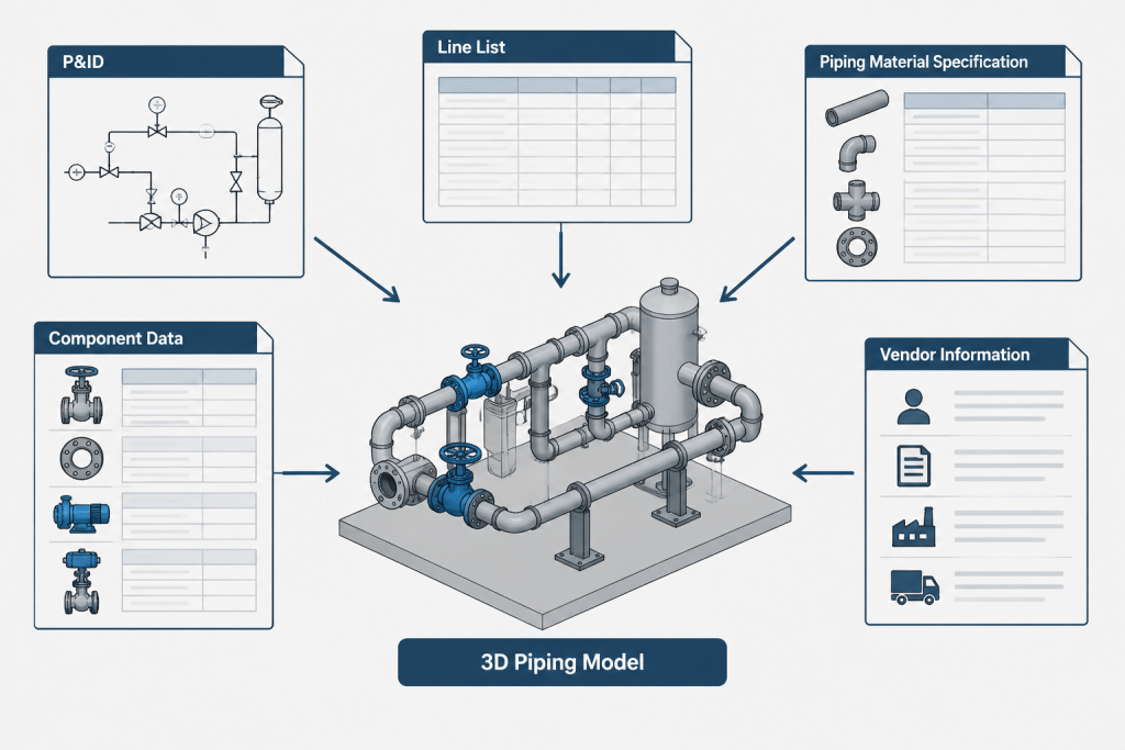
A Controlled P&ID-to-3D Workflow
1. Identify the Functional Item
Read the symbol together with its tag, notes, line number, instrument connections, and nearby process relationships. Determine what the item must do before selecting a physical CAD object.
2. Check the Line Data
Use the line list and piping specification to confirm nominal size, material class, service, insulation status, and other relevant attributes. Resolve conflicts between documents instead of choosing whichever value is easiest to model.
3. Select the Physical Component Type
Choose a component only after its permitted type and connections are established. For a valve, this may require checking the valve description, body style, ends, operator, flow direction, and tag data. For an instrument connection, determine whether the model must include the process fitting, root valve, manifold, tubing interface, or only a reserved connection point.
4. Establish the Required Level of Detail
Not every project phase requires vendor-accurate geometry. Early models may use controlled generic envelopes, while fabrication or final coordination may require verified dimensional data. The important point is to match model detail to its intended use and document any limitations.
5. Orient for Function and Access
Check flow direction where relevant, then review operation, visibility, drainage, venting, actuator access, removal paths, and surrounding structures. The correct schematic item can still be incorrectly installed in the model if orientation is not reviewed.
6. Reconcile Tags and Connectivity
Verify that every modeled tagged item maps back to the current P&ID and that required branches and instrument connections are present. Also check the reverse: a model may contain temporary or duplicated components that no longer appear on the approved diagram.
Handling Information That Is Not Yet Available
Missing information should be managed explicitly rather than filled with an unverified assumption. A practical placeholder record can identify:
- The associated P&ID tag and line number.
- The known function and connection points.
- The source used for provisional geometry.
- Properties awaiting confirmation.
- The discipline or supplier responsible for resolving them.
- The layouts affected if the final component changes.
Space reservations should account for more than the provisional body. Operators, actuators, covers, screens, cartridges, bolting access, and removal paths may govern the layout. These envelopes should be based on project or supplier information when available, not on an arbitrary enlargement of a symbol.
Reviewing the Completed Translation
A useful review separates functional checks from geometric checks. The functional review confirms that the model contains the correct tagged items, branches, flow relationships, and specification transitions. The geometric review checks physical compatibility, orientation, accessibility, and dimensional control.
- Does each modeled item correspond to the intended P&ID function?
- Are size, line class, and end connections supported by controlled project data?
- Are reducers, flanges, branch fittings, and companion components included where physically required?
- Is directional equipment aligned with the intended flow?
- Can operators and removable parts be reached and withdrawn?
- Are generic or estimated components visibly classified as preliminary?
- Have P&ID revisions been reconciled with the model and component list?
The Key Principle
The P&ID defines what the piping system is intended to do; the 3D model defines how the physical system occupies and connects within space. Neither document should be forced to perform the other’s role. Reliable CAD work comes from linking the schematic symbol to the correct specification, component data, interfaces, and layout requirements—without treating the symbol itself as dimensional evidence.
Document Authority and Conflict Resolution
Reliable translation depends on knowing which document controls each property. The P&ID may control the required function and process relationship, while a piping material specification controls permitted component construction and connections. Equipment, valve, and instrument documents may define interfaces or arrangements that the P&ID does not show.
When controlled sources disagree, the discrepancy should be resolved through the project review process rather than silently corrected in the model. A convenient catalog selection does not override a line class, data sheet, equipment interface, or approved process requirement. Recording the conflict also helps prevent the same unsupported assumption from appearing in material reports, isometrics, or later model revisions.
Keep Functional Identity Separate from Model Geometry
A useful CAD record separates what is known about an item from how it is currently represented. The functional identity includes the tag, service relationship, line association, and required action. The geometric representation includes ports, body envelope, operator arrangement, and reserved access space.
This separation allows preliminary geometry to be replaced without losing the item’s identity or process purpose. It also makes status clearer to reviewers: a component may be functionally confirmed while its exact physical configuration remains provisional.
Coordinate the Model with Downstream Deliverables
The completed translation may affect more than the visual model. Component choices and connection arrangements can influence adjoining pipe geometry, joint locations, material extraction, isometric output, support coordination, access reviews, and equipment-interface checks. Before a placeholder is promoted to an approved component, confirm that dependent deliverables receive the same verified information.
Revision review should work in both directions. P&ID changes must be assessed for physical model impact, and discoveries made during layout should be returned for process or specification review when they reveal missing branches, incompatible interfaces, inaccessible equipment, or unclear component requirements.
Practical Handoff Checklist
- Identity: Confirm that the CAD item retains the correct tag, line association, and process function.
- Authority: Identify the controlled source for component type, connection arrangement, interface, and geometry.
- Status: Distinguish verified components from generic or provisional representations.
- Dependencies: Record which routes, supports, structures, interfaces, or access zones could be affected by a later change.
- Revision: Reconcile updates across the P&ID, model, line information, component records, and related deliverables.
Frequently Asked Questions
Does a P&ID valve symbol define the valve body style?
Not by itself. The symbol primarily communicates function and connectivity. Body style, end connections, operator arrangement, and physical envelope must be established from the applicable piping specification, data sheet, component description, or verified supplier information.
Can the orientation shown on a P&ID be copied into the model?
The diagram’s page orientation should not be treated as a plant orientation unless the project documentation explicitly makes that requirement. Model orientation must account for flow direction, operation, access, drainage, venting, connected instruments, and removal needs.
What should be done when the final component has not been selected?
Use a controlled placeholder that preserves the known function, tag, and connection intent. Mark its geometry and unresolved properties as provisional so other users do not mistake the representation for verified component data.
Why can a correct P&ID still produce an incorrect 3D model?
A model can reproduce the intended connectivity while using an incompatible component, unsupported connection, incorrect orientation, or inadequate access envelope. Functional verification and geometric verification are therefore separate but related reviews.
Should reducers and companion fittings be inferred from the symbol?
No. Review line data, instrument details, equipment connections, component interfaces, and the piping specification. Add physical transition components only when supported by controlled design information.
How should conflicts between the P&ID and model data be handled?
Record and route the discrepancy through the project’s review process. Do not choose a value merely because it is already present in the catalog or easier to model. The responsible disciplines must establish which controlled information applies.