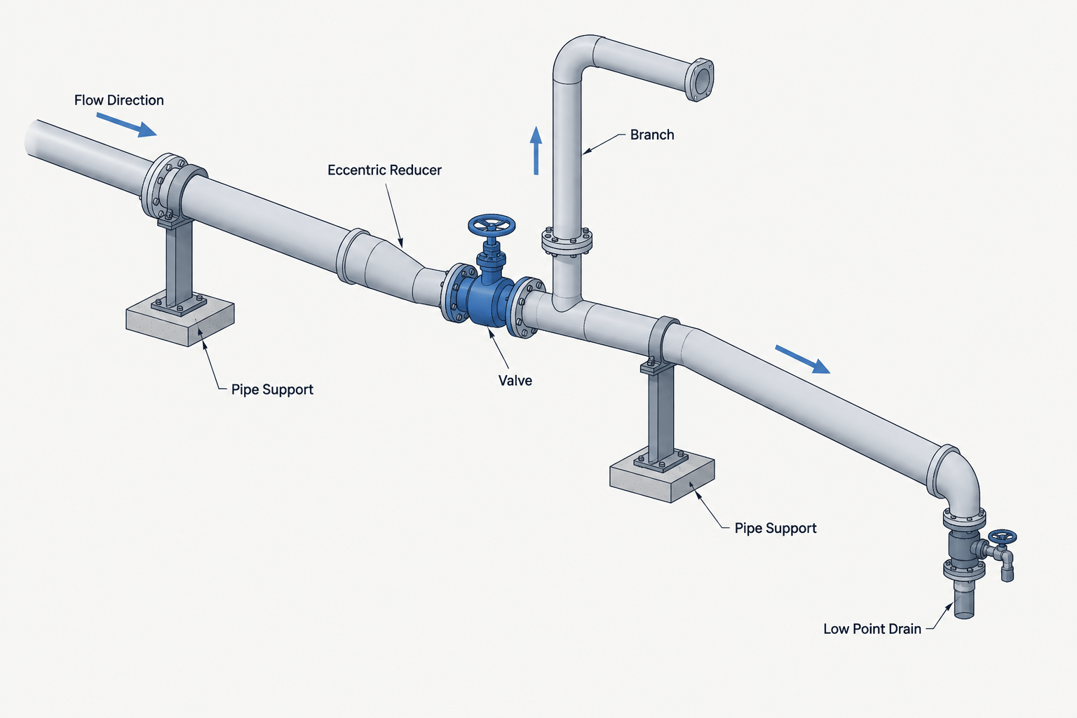
A sloped pipe centerline does not automatically create a drainable piping system. Liquid can remain trapped by a reducer, valve body, branch connection, fitting transition, support deflection, or an incorrectly placed drain. These pockets may interfere with cleaning, maintenance, product changeover, freeze protection, testing, or process operation.
CAD designers therefore need to evaluate more than the route shown between two elevations. A useful drainability review follows the intended liquid path through the actual component sequence and asks whether every local low point has an acceptable route to a designated drain or destination.
What drainable piping means
A drainable piping layout allows liquid to move toward an intended collection point under the available driving force. In some systems, gravity is expected to do most of the work. In others, pressure, purging, blowing, or another operating procedure may assist drainage. The required result depends on the service and project criteria.
Drainability should not be confused with these related concepts:
| Concept | Primary question | Typical CAD concern |
|---|---|---|
| Pipe slope | Does the route rise or fall in the required direction? | Centerline elevations, slope notes, and support levels |
| Drainability | Can retained liquid reach an acceptable outlet? | Local low points, bore transitions, valve bodies, and drain locations |
| Ventability | Can displaced gas escape as liquid enters or leaves? | High points, trapped gas volumes, and vent connections |
| Flushability | Can flow reach and sweep the relevant internal surfaces? | Branches, dead ends, valve cavities, and flow path |
A line can satisfy a drawing slope note and still contain an isolated pocket. Conversely, a system that is not completely gravity-drainable may be acceptable if its operating or maintenance procedure intentionally removes the remaining liquid. The CAD model should communicate the geometry clearly enough for engineering to make that determination.
Why centerline slope is not enough
Pipe routing is commonly controlled by centerline elevations because fittings and connected equipment are located from their centerlines. Liquid, however, responds to the internal flow surface. The critical path for drainage is closer to the pipe invert—the lowest internal surface—than to the centerline alone.
If the outside diameter remains constant along a sloped run, the centerline and bottom surfaces generally follow the same overall direction. Component changes can interrupt that relationship. A larger valve body may contain a lower internal cavity. A change in pipe size may shift the bottom of the bore. A fitting or weld transition may introduce a local ledge that is not represented in a simplified model.
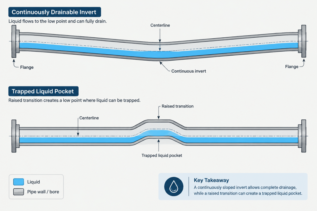
For this reason, drainability reviews should combine centerline data with component geometry and connection information. A generic valve symbol or simplified solid cannot establish the internal contour of a purchased valve.
Common sources of liquid pockets
Eccentric reducers in the wrong orientation
An eccentric reducer can preserve either the top-side or bottom-side alignment of connected piping, depending on its orientation. Where bottom continuity controls drainage, the selected orientation should support that intent. The correct choice is service-dependent; suction piping, vapor management, process drainage, and equipment nozzle geometry can lead to different decisions.
Do not rely only on the reducer’s appearance in plan. Confirm its rotational orientation in the model and communicate it on the isometric with the project’s approved notation or an unambiguous graphical representation.
Valve bodies and end connections
Some valves have internal cavities, seats, or body contours that retain liquid even when the adjacent pipe slopes correctly. Stem direction and body orientation may also affect whether the cavity can drain. A line-sized CAD envelope usually does not reveal this behavior.
When complete drainage matters, obtain verified manufacturer information and review the intended installed orientation. Do not infer internal drainability from face-to-face length or an external valve shape.
Branch connections and unused legs
A branch taken from the bottom of a line may serve as a drain, but its effectiveness depends on the actual intersection, branch slope, valve location, and downstream destination. Side branches, instrument connections, bypasses, and capped extensions can create retained volumes.
Review each branch as a flow path rather than treating it as a symbol attached to the main. A small connection can still create an operationally important pocket or dead end.
Changes in wall thickness or bore
Nominally compatible components do not always have identical internal diameters. Pipe schedule changes, fitting bores, flange hubs, weld preparations, linings, and fabrication transitions can produce internal steps. CAD models often align outside surfaces or centerlines without representing these details.
Such transitions may be insignificant for one service and critical for another. Flag uncertain bore transitions for engineering or fabrication review rather than adding invented internal geometry.
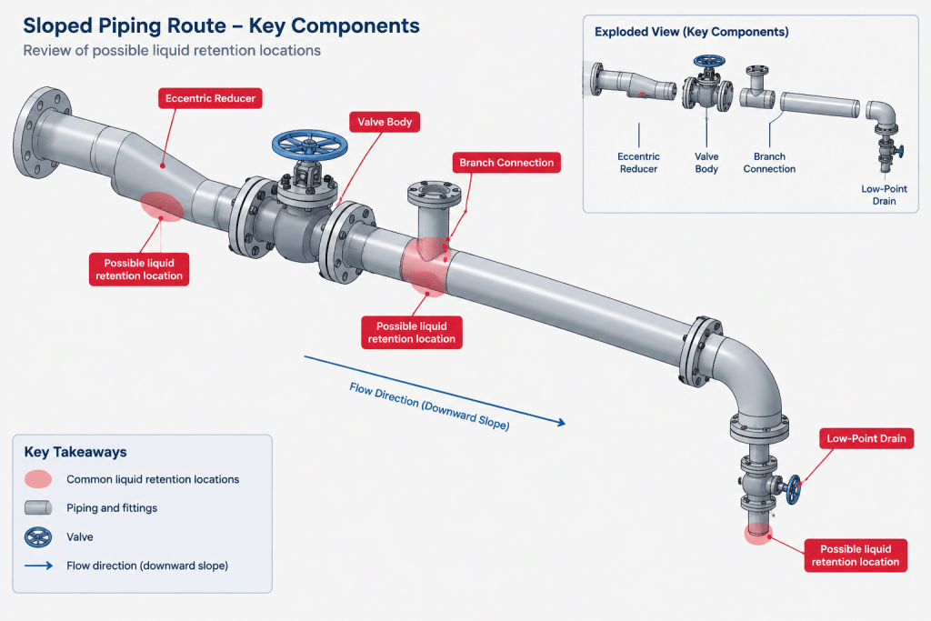
Low points created by routing
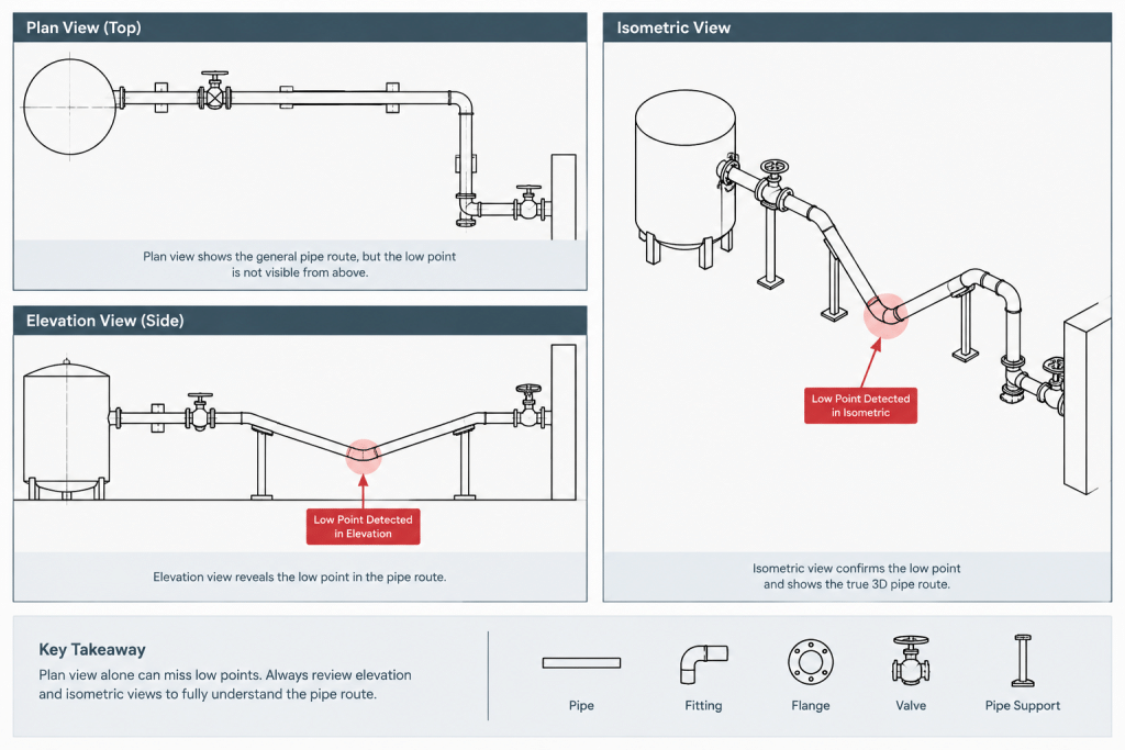
Rolling offsets, equipment approaches, flexible loops, field-fit sections, and crossings can create local low points that are easy to miss in plan. A route may appear continuously sloped in one view while changing elevation unexpectedly in another.
Sections, isometric views, and elevation reports are useful for checking the full three-dimensional path. Review fitting tangent regions as well as straight pipe endpoints.
A practical CAD drainability review workflow
1. Establish the drainage objective
Identify what must be drained, where the liquid is expected to go, and what provides the driving force. Confirm whether the objective is routine process drainage, maintenance drainage, test-water removal, cleaning, winterization, or another function. These objectives are not automatically interchangeable.
2. Trace the intended path from every source volume
Start at equipment nozzles, vessel connections, branch ends, valve cavities, and other volumes that can contain liquid. Follow the path to the designated drain point. At every component, ask whether the internal flow path remains open in the required operating or maintenance state.
3. Review elevations in the direction of drainage
Check centerline, bottom-of-pipe, or invert elevations as appropriate for the available data. Look for reversals, flat segments, and isolated lows. Avoid judging the route solely from a slope arrow; compare the actual endpoint elevations and intervening geometry.
4. Inspect every size and component transition
Review reducers, valves, strainers, specialty items, flanges, branch fittings, and equipment nozzles. Confirm reducer rotation and identify components whose internal geometry is unknown. Manufacturer outlines are useful for space planning, but drainability may require sectional or product-specific information.
5. Check support assumptions
A perfectly sloped model represents nominal geometry. The installed line may respond to support elevations, fabrication variation, loading, thermal movement, and deflection. Coordinate critical drainage routes with the support design so the intended fall is not defeated by support placement or movement.
6. Verify the drain connection itself
Confirm that the drain begins at the effective low point and that its downstream route is usable. Include isolation valves, caps, plugs, hoses, funnels, closed-drain headers, or collection equipment where they are part of the design. Check access for operation and maintenance.
7. Record unresolved assumptions
If valve internals, vendor nozzle details, field elevations, or fabrication transitions are unknown, identify them as review items. A visible assumption is safer than a falsely precise model.
How to document drainability clearly
The model, isometric, and supporting documents should work together. Depending on project practice, useful information may include:
- Flow or drainage direction where it is not obvious.
- Pipe slope and the direction in which it applies.
- Controlling endpoint or low-point elevations.
- Eccentric reducer orientation.
- Drain and vent connection identification.
- Valve orientation when it affects the intended drainage path.
- References to operating, flushing, or maintenance requirements maintained elsewhere.
- Review notes for vendor components with unknown internal geometry.
Avoid dimensioning the same sloped run from several competing controls. Establish the governing elevation or datum, then provide enough information to reproduce and inspect the route without creating a closed or contradictory dimension chain.
Model detail and verification limits
It is rarely efficient to model every internal bore, weld root, or valve cavity throughout a plant. The appropriate level of detail depends on the consequence of retained liquid and the stage of design. General routing models may use nominal envelopes, while critical systems may need targeted sectional studies or vendor geometry.
The important distinction is between geometry that has been verified and geometry used only as a placeholder. A CAD component that looks complete can still omit the internal features controlling drainage. Component metadata or review notes can identify items requiring confirmation without implying unverified performance.
Drainability review checklist
- Is the drainage objective defined?
- Is the destination available in the relevant operating or maintenance condition?
- Does the actual route maintain the intended fall?
- Have local low points been checked in multiple views?
- Are eccentric reducers rotated correctly for the design intent?
- Could valves or specialty components retain liquid?
- Are branches, bypasses, instrument legs, and capped ends included in the review?
- Have bore changes and internal steps been considered?
- Can gas enter or escape as required for drainage?
- Do support elevations and expected movement preserve the intended route?
- Are drain valves and closures accessible?
- Are unknown vendor or field conditions clearly flagged?
A reliable drainable piping layout is produced by tracing the real liquid path, not merely by applying a slope note. CAD provides the geometry needed to expose potential pockets, but component internals, operating conditions, supports, and field tolerances must also be considered before drainability is accepted.