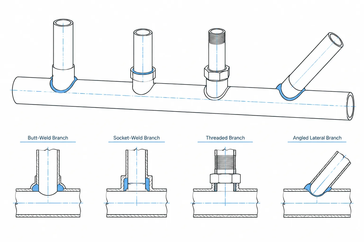
Branch outlet fittings provide a compact way to connect a smaller branch to a pipe, elbow, or other compatible run component. They are common where a conventional tee is unnecessary, unavailable in the required configuration, or less practical for the layout. Although the finished connection may occupy little space, it carries several design and fabrication variables that must be represented correctly in CAD.
A reliable model must distinguish the outlet fitting from the opening in the run pipe, the branch-end connection, and any separate branch piping. Treating the assembly as a generic tee can obscure weld locations, material requirements, branch orientation, and cut-length information.
What Is a Branch Outlet Fitting?
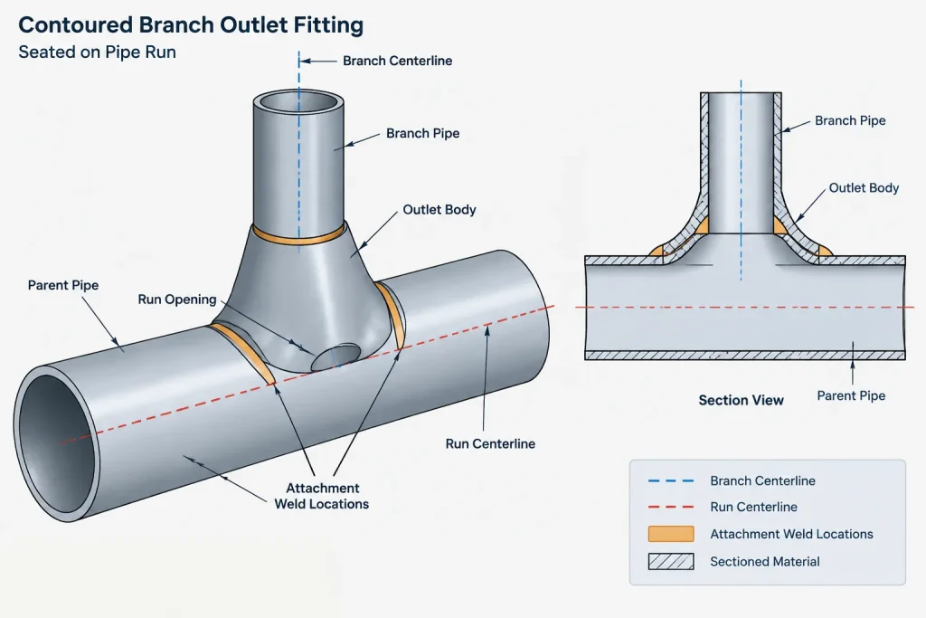
A branch outlet fitting is a contoured component attached to the outside of a run pipe or another permitted parent component. Its base is shaped to fit the supporting surface, while its outlet provides the connection for the branch. Depending on the selected type, the branch connection may be butt-welded, socket-welded, threaded, or supplied in another project-approved form.
The fitting and the opening in the run work together as an assembly. The run is cut or prepared, the fitting is positioned over the opening, and the fitting is attached using the required weld detail. The fitting may also contribute reinforcement around the opening, but its suitability cannot be determined from appearance alone. Selection must follow the piping specification, design conditions, applicable design rules, material requirements, and verified manufacturer data.
Common Outlet Types and Their CAD Implications
| Outlet description | Typical branch connection | Important CAD consideration |
|---|---|---|
| Butt-weld outlet | Branch pipe is butt-welded to the outlet end | Show the outlet fitting separately from the branch pipe and identify both weld locations |
| Socket-weld outlet | Branch pipe enters a socket and is fillet welded | Account for insertion geometry and the project-required assembly condition |
| Threaded outlet | Branch component engages internal threads | Do not infer visible assembled length from nominal component length alone |
| Nipple-style outlet | Extended neck connects directly to downstream piping or a component | Verify whether the neck is integral to the outlet or a separate nipple |
| Lateral outlet | Branch departs at an oblique angle | Control the true branch axis, rotation, and developed opening location |
| Elbow outlet | Outlet is attached to an elbow where permitted | Model the actual elbow surface and verify the approved attachment location |
Terms such as weldolet, sockolet, and threadolet are widely used as shorthand in industry, but naming conventions can vary among specifications, catalogs, and project databases. A component description should communicate the connection type rather than relying only on an informal family name.
The Geometry That the Model Must Control
Run centerline and branch centerline
The branch axis normally points toward the run axis for a radial outlet. That relationship should be established by geometry, not by visually placing the fitting against the outside surface. If the run size, branch size, or fitting family changes, a loosely placed component may no longer remain centered.
A lateral outlet is different. Its branch axis intersects the run at a specified angle and must also be clocked around the run. Both the angle and circumferential orientation are necessary to locate it fully.
Contoured base
The outlet base is shaped for a particular parent surface. A fitting modeled for one run diameter should not be stretched to fit another. Scaling can distort the body, weld interface, outlet bore, and end geometry. Use verified geometry for the selected run and branch combination, or use an intentionally simplified symbol linked to correct catalog data.
Outlet projection
The distance from the run centerline or outside surface to the branch-end connection affects routing and branch cut length. This projection is not safely derived from a generic envelope. It should come from an approved dimensional source associated with the actual fitting selection.
Run opening
The opening in the run is fabrication information, not merely a visual hole in the model. Its shape and preparation can depend on the fitting, parent surface, welding procedure, and fabricator practice. CAD users should not invent a cutout by matching the visible outlet bore. When opening dimensions are needed, obtain them from controlled fabrication or manufacturer information.
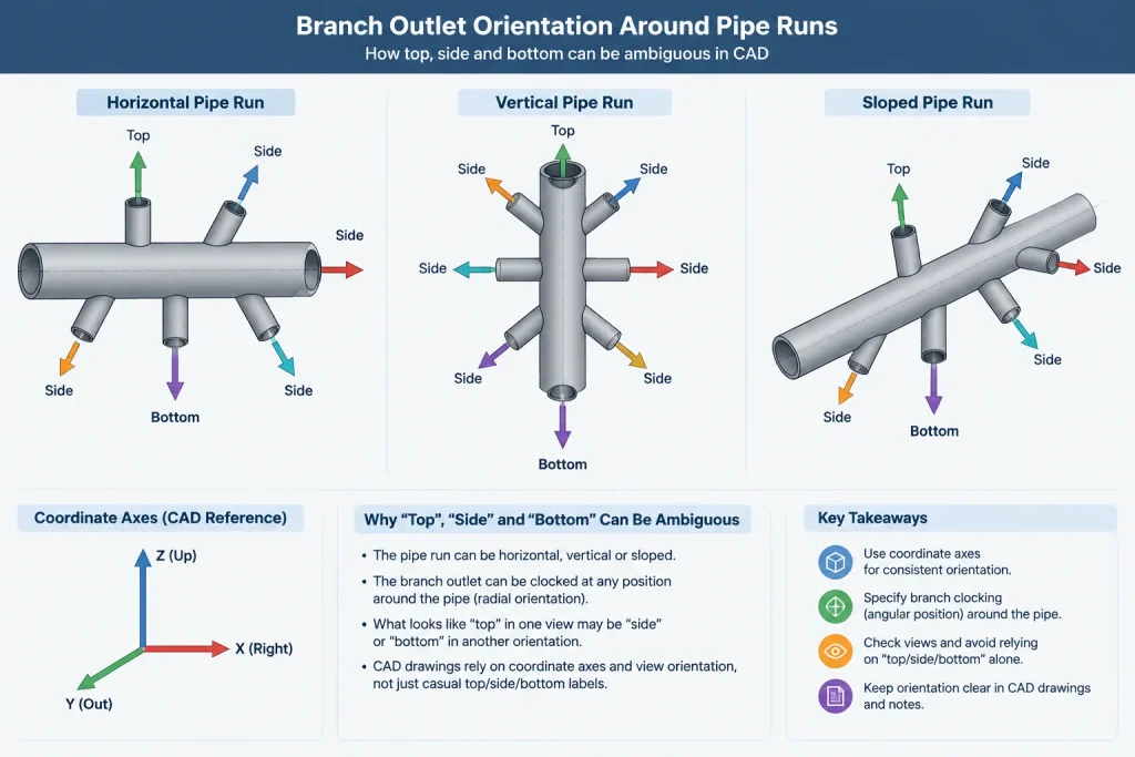
Orientation and Clocking
For a straight horizontal run, descriptions such as top, bottom, and side may be sufficient during early layout. They become ambiguous on sloped, vertical, or skewed piping. Production documentation should use a method that can be checked independently, such as coordinates, a branch centerline direction, an angular orientation tied to a defined reference, or dimensions from established datums.
Orientation also affects more than appearance. The designer may need to consider:
- Drainability or venting intent;
- Access to a threaded or socket-weld branch component;
- Clearance for insulation and welding;
- Interference with nearby outlets, seams, supports, or attachments;
- Space for inspection and examination activities;
- Branch loads and any required support close to the connection.
A CAD model can expose spatial conflicts, but it does not establish that the branch connection is structurally acceptable. Loads, reinforcement, attachment placement, and parent-pipe suitability remain engineering checks.
How to Represent the Assembly at Different Levels of Detail
In an early routing model, an outlet may be represented by a branch node, an approximate envelope, and connection metadata. This can be sufficient for line routing and preliminary clash review if the simplification is clearly understood.
A detailed design model should normally distinguish the parent pipe, outlet fitting, branch pipe, and connected valve or instrument item. Connection ports should identify the run-side attachment and branch-side end type. The component record should carry the data needed by the material workflow without embedding unverified dimensions in manually drawn solids.
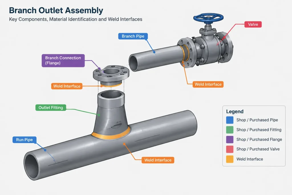
A fabrication model may also show weld locations, end preparation, insertion relationships, spool ownership, and the controlled opening. Whether those features belong in the design model or in fabricator-developed documentation depends on the project handoff process.
Isometric and Drawing Documentation
An isometric should make it possible to identify what is purchased, what is cut, and what is welded. For an outlet branch, review the drawing for the following:
- The outlet fitting is listed as a separate material item when it is separately purchased.
- The run-to-outlet attachment is not confused with the branch-end weld.
- The branch connection type agrees with the piping specification.
- The outlet location is controlled along the run.
- The branch orientation can be reconstructed without measuring the drawing pictorially.
- The branch pipe cut length uses the correct fitting projection or insertion basis.
- Shop and field responsibilities are identified consistently with the spool plan.
- Any required special fabrication note is linked to approved information.
On a single-line isometric, the fitting symbol will not describe its complete physical shape. The item callout, end-connection data, bill of materials, and weld information therefore carry much of the technical meaning.
Frequent Modeling and Detailing Errors
- Substituting a tee: A tee may produce a connected centerline model, but it changes component identity, takeout, weld arrangement, and material reporting.
- Using the wrong parent diameter: The fitting may touch the pipe graphically while its contoured base is incompatible with the selected run.
- Ignoring end connection: Butt-weld, socket-weld, and threaded outlets create different branch assembly conditions.
- Scaling a generic block: Uniform scaling does not preserve verified fitting geometry or connection metadata.
- Placing the branch by eye: Small angular errors can move the remote end of the branch and cause coordination problems.
- Double-counting components: An extended-neck outlet may be mistaken for an outlet plus a separate nipple.
- Inventing the opening size: A visually plausible hole is not controlled fabrication information.
- Omitting weld distinctions: The run attachment and branch connection may require separate weld records and inspection tracking.
A Practical CAD Review Workflow
- Confirm that an outlet fitting is permitted by the line specification and branch connection rules.
- Verify the parent component, run size, branch size, material, and branch-end connection.
- Select verified component geometry or a controlled simplified representation.
- Place the outlet using the run axis, branch axis, and a defined orientation reference.
- Check the fitting projection and resulting branch cut-length basis.
- Review nearby welds, fittings, supports, insulation, and access requirements.
- Confirm that the isometric symbol, item description, weld records, and bill of materials agree with the model.
- Flag any run-opening detail that requires manufacturer, engineering, or fabricator confirmation.
Key Takeaway
Branch outlet fittings should be modeled as connection assemblies, not as decorative lumps on a pipe. The important controls are component type, compatible parent surface, branch-end connection, centerline relationship, orientation, projection, weld identity, and material data. When those elements remain synchronized, the CAD model can support routing, isometric generation, purchasing, fabrication planning, and review without pretending to replace the engineering checks behind the branch connection.