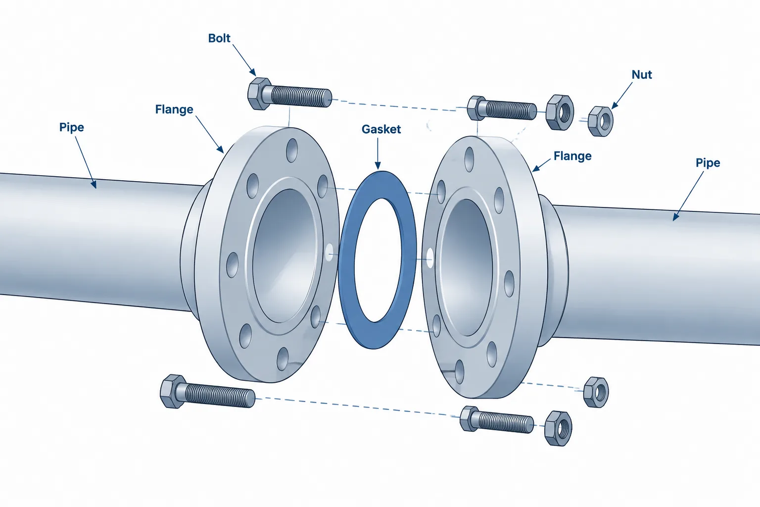
Piping gaskets in CAD should be managed as functional parts of flanged connections, not merely as thin graphical separators. Their representation must support the intended deliverable while remaining coordinated with flange faces, fasteners, piping specifications, material records, and joint dimensions.
This guide explains how to choose an appropriate level of gasket geometry, distinguish nominal data from assembly assumptions, maintain flange compatibility, and check the connection across the model, drawings, isometrics, and bill of material. Final gasket selection must follow approved project requirements rather than appearance or an unverified catalog match.
A gasket may occupy only a thin space between two flange faces, but it affects piping dimensions, bolting, material control, assembly, and maintenance. Treating every gasket as a generic line in CAD can hide important differences in sealing form, outside envelope, thickness, and flange compatibility.
The goal is not to reproduce every winding, filler layer, or surface feature in a piping model. It is to represent the gasket accurately enough for the intended task and to connect that geometry with the correct specification data. A layout model may need only a reliable joint gap, while a fabrication detail or bill of material may require a defined gasket type, size, material description, and identification tag.
What the gasket controls in a flanged joint
A gasket provides the sealing element between compatible flange faces. The completed joint also includes the flanges, fasteners, and any project-specific washers or isolation components. These parts function as an assembly rather than as independent items.
From a CAD and documentation perspective, the gasket can influence:
- The face-to-face position of the connected flanges
- The overall stack used when determining fastener length
- Clearance around the outside of the joint
- The usable opening through the connection
- Material takeoff and procurement descriptions
- Installation sequence and replacement planning
- Compatibility with flange facing and service requirements
The gasket should therefore be associated with the joint, not left as an untracked graphical mark. If one flange moves, is replaced, or changes type, the gasket data should be reviewed with it.
Common gasket forms and how they differ in CAD
Gasket selection is governed by the piping specification, flange design, service conditions, and applicable project requirements. CAD users should not infer the correct gasket solely from pipe size or pressure class. However, understanding the broad forms helps determine what geometry and metadata should be shown.
| Gasket form | Typical CAD concern | Documentation concern |
|---|---|---|
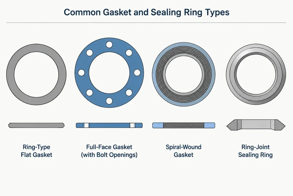
| Ring-type flat gasket | Located within the bolting circle rather than extending across the full flange face | Material, thickness, size, and flange compatibility |
| Full-face gasket | Outside profile and bolt openings may matter in detailed views | Hole pattern, material, thickness, and matching flange form |
| Spiral-wound gasket | Usually modeled as a simplified annular component | Winding, filler, inner-ring, and outer-ring requirements where applicable |
| Jacketed or other engineered gasket | Envelope may be simple even when construction is specialized | Exact specification and manufacturer data become especially important |
| Ring-joint sealing ring | Located by the grooves in mating ring-type-joint flanges | Correct ring designation, material, and groove compatibility |
| Flange isolation gasket assembly | May require a broader joint representation because sleeves and washers are involved | All assembly components must remain coordinated as a kit |
These categories are not interchangeable. A similar-looking annular CAD object does not demonstrate that the seal is suitable for a particular flange or service.
Choose the model detail level deliberately
Schematic and early layout models
During routing studies, a gasket may be represented by a joint node, a thin spacer, or an attribute attached to a flange connection. The essential requirement is that the software or designer accounts for the intended connection stack consistently. A zero-thickness representation can create accumulated dimensional errors if flange positions are later treated as fabrication coordinates.
Detailed 3D piping models
A detailed model should normally use simplified outer and inner cylindrical boundaries plus the specified nominal thickness. Decorative surface detail rarely improves coordination. More useful properties include gasket type, nominal pipe size, flange class or joint designation, material description, piping specification, and item code.
The gasket object should share the flange axis and be seated between the correct connection faces. It should not merely be placed near the joint as an unconnected solid.
Fabrication and assembly details
A fabrication detail may need to distinguish a full-face profile from a ring profile, identify an isolation assembly, or show the order of joint components. Enlarged details can communicate this without adding excessive detail to the main model. Use notes and item callouts for construction information that cannot be communicated reliably by simplified geometry.
Nominal thickness versus assembled thickness
Gasket thickness requires careful terminology. A catalog or project specification may identify an uncompressed or nominal thickness, while the installed joint experiences compression when the fasteners are tightened. The final compressed condition depends on the gasket construction, flange condition, assembly procedure, and other controlled factors.
CAD should not invent a compressed value. For general layout, use the project-approved dimensional basis and state that basis when it affects coordinates or bolt calculations. If an analysis or specialist calculation supplies an installed thickness, preserve the source and purpose of that value rather than silently replacing the catalog thickness.
This distinction matters when several flanged joints occur in a dimension chain. Small assumptions can accumulate across equipment trains, valve assemblies, removable spools, and prefabricated piping.
Gasket inside and outside boundaries
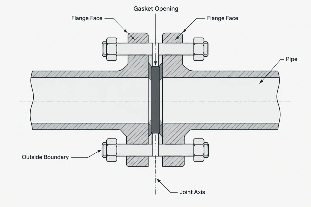
The gasket inside diameter should not be confused with the pipe bore. Pipe inside diameter varies with wall thickness, while the gasket opening is selected as part of a flange joint system. The two may not align exactly.
The outside boundary also has practical importance. A ring gasket generally remains inside the bolt pattern, while a full-face gasket extends farther outward and includes bolt openings. Engineered gasket assemblies may include centering or retaining features that establish a larger envelope than the active sealing area.
For ordinary plant-layout clash detection, detailed gasket edges may not be critical because flange and bolt envelopes are usually larger. For tight packaged equipment, special joints, and installation details, however, the correct outer profile can help prevent interference and assembly mistakes.
Keeping the gasket aligned with the flange pair
A reliable CAD workflow treats the two flanges and gasket as one coordinated connection. Review the following relationships:
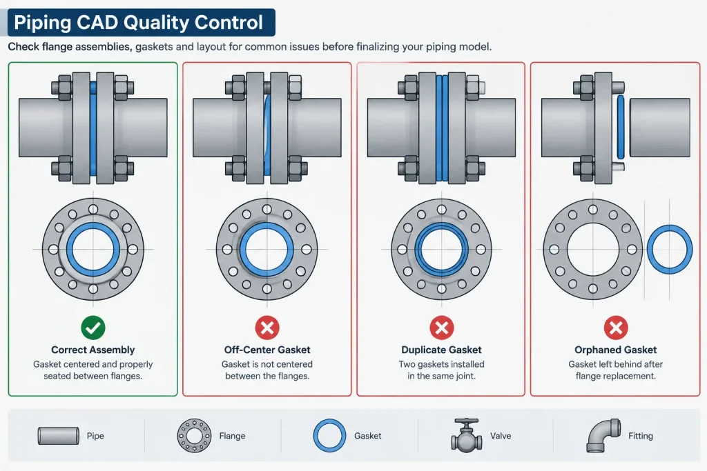
- Both flange faces are parallel and share a common axis.
- The gasket is centered on the joint axis.
- The gasket is associated with the intended pair of mating flanges.
- The facing types and sealing system are compatible according to the governing specification.
- The gasket is not duplicated where intelligent components already generate one automatically.
- The gasket thickness used by the model matches the dimensional basis used for the joint.
- Joint changes trigger a review of fasteners and adjacent spool dimensions.
A common modeling error occurs when a flange is replaced but the original gasket remains as an independent object. The resulting model may look acceptable from a distance while the item code, dimensions, or seal type no longer matches the connection.
What to place in the component data
Geometry alone is not enough for procurement or fabrication. The gasket record should carry only verified fields supported by the project specification, component catalog, or approved supplier data. Useful fields may include:
- Item or commodity code
- Nominal size
- Joint or flange designation
- Gasket construction or form
- Material description
- Nominal thickness
- Inner- and outer-ring requirements where relevant
- Applicable piping material specification reference
- Quantity and unit of measure
- Special service or isolation designation
Avoid free-text descriptions that vary from one modeler to another. Controlled catalog descriptions make it easier to reconcile the 3D model, isometric bill of material, purchasing data, and field installation package.
Drawing and isometric representation
On a piping isometric, a gasket is often represented symbolically at the flanged joint and listed in the material takeoff. The symbol does not need to resemble the physical construction in detail. Its purpose is to identify that a separate sealing item is required and to connect the joint with the correct material entry.
On plans and elevations, very thin gasket geometry may disappear at normal drawing scales. Do not exaggerate thickness in a dimensionally controlled view unless the graphic convention is clearly understood. A callout, item bubble, or enlarged detail is usually safer than altering physical geometry for visibility.
For assembly drawings, show the gasket in the correct sequence between the flange faces. When an isolation kit or multi-part sealing system is used, identify the related sleeves, washers, and other components so they are not separated during procurement or installation.
Practical gasket QA checklist
- Confirm that every required flanged joint has one intended sealing item.
- Check that the gasket size and joint designation match both mating flanges.
- Verify the gasket form and material against the piping specification.
- Confirm that modeled thickness is based on an approved source.
- Review special facings, ring-joint grooves, and isolation assemblies separately.
- Check that changes to valves, equipment nozzles, or flange types have updated the gasket record.
- Recalculate or reverify fastener length when the joint stack changes.
- Compare the model quantity with the isometric and bill of material.
- Remove duplicate or orphaned gasket objects from revised connections.
- Flag unresolved data rather than selecting a visually similar catalog item.
A small component with joint-level consequences
Good gasket modeling is less about producing intricate 3D geometry and more about preserving the integrity of the flanged connection. The CAD object, flange faces, fastener stack, material specification, and bill of material must describe the same assembly.
Use simplified geometry where it serves the drawing, but do not simplify away the data that controls selection and installation. When dimensions or construction details affect fabrication, verify them against the governing project specification, applicable standard, or approved manufacturer information before issuing the model or drawing.
Build the gasket record from the joint requirements
A dependable workflow begins with the complete flange connection. The modeler should identify the mating flange arrangement, applicable piping specification, sealing form, and approved dimensional basis before assigning a gasket catalog item. This prevents the geometry from becoming the source of an otherwise unsupported technical decision.
The resulting CAD component may remain geometrically simple, but its relationship to the joint should be explicit. The gasket should move with the connection, appear in the required material output, and remain traceable to controlled specification data.
Recommended model-to-document workflow
- Resolve the connection: confirm which flange faces are intended to mate and whether either side has changed during design development.
- Apply controlled selection data: use the approved piping specification, project catalog, or supplier information rather than selecting by visual similarity.
- Place the component: align the gasket with the flange axis and seat it at the defined connection location.
- Check the joint stack: coordinate the gasket basis with flange positions, fastener requirements, removable spools, valves, and equipment connections.
- Populate the record: use consistent item descriptions and verified attributes that can pass into drawings and material reports.
- Review the outputs: compare the model, isometric symbol, assembly detail, and bill of material for omissions, duplication, and inconsistent descriptions.
Control gasket changes as connection changes
A gasket revision should not be treated as an isolated catalog edit. Changes to flange type, facing, valve ends, equipment nozzles, isolation requirements, or joint construction can affect the sealing item and associated fasteners. The connection should therefore be rechecked as an assembly whenever one of its controlled components changes.
Before issue, unresolved gasket information should remain visibly flagged in the project workflow. Replacing uncertainty with a plausible-looking component can produce a coordinated-looking model while leaving procurement and installation data incorrect.
Frequently asked questions about piping gaskets in CAD
Does every gasket need detailed geometry in a piping model?
No. The necessary detail depends on the purpose of the model. Layout work may use simplified geometry or connection data, while fabrication and assembly documents may require a recognizable profile and component sequence. The model must still retain the verified gasket identity and dimensional basis needed by downstream deliverables.
Can the gasket be omitted if the flanges appear to touch?
Only if the modeling system intentionally handles the gasket through connection logic and still accounts for the required joint data. Omission must not cause the flange location, joint stack, material takeoff, or fastener review to ignore the sealing item.
Is the gasket opening the same as the pipe inside diameter?
Not necessarily. Pipe bore is influenced by pipe wall, while the gasket opening belongs to the selected flange-joint system. Use approved gasket and flange information rather than deriving the opening directly from the modeled pipe bore.
Should CAD use nominal or compressed gasket thickness?
Use the project-approved dimensional basis. CAD should not estimate an installed or compressed thickness. If a specialist calculation or approved source defines another basis, record its purpose and apply it consistently to the affected joint.
How should gasket substitutions be checked?
Revalidate the substitute against both mating flanges, the piping specification, service requirements, joint construction, material description, dimensional basis, and associated fasteners. Similar geometry alone does not establish compatibility.
Why can the model and bill of material disagree?
Common causes include orphaned gasket objects, automatically generated components combined with manually placed duplicates, uncontrolled free-text descriptions, or flange revisions that did not update the joint record. A coordinated joint review is more reliable than checking geometry alone.