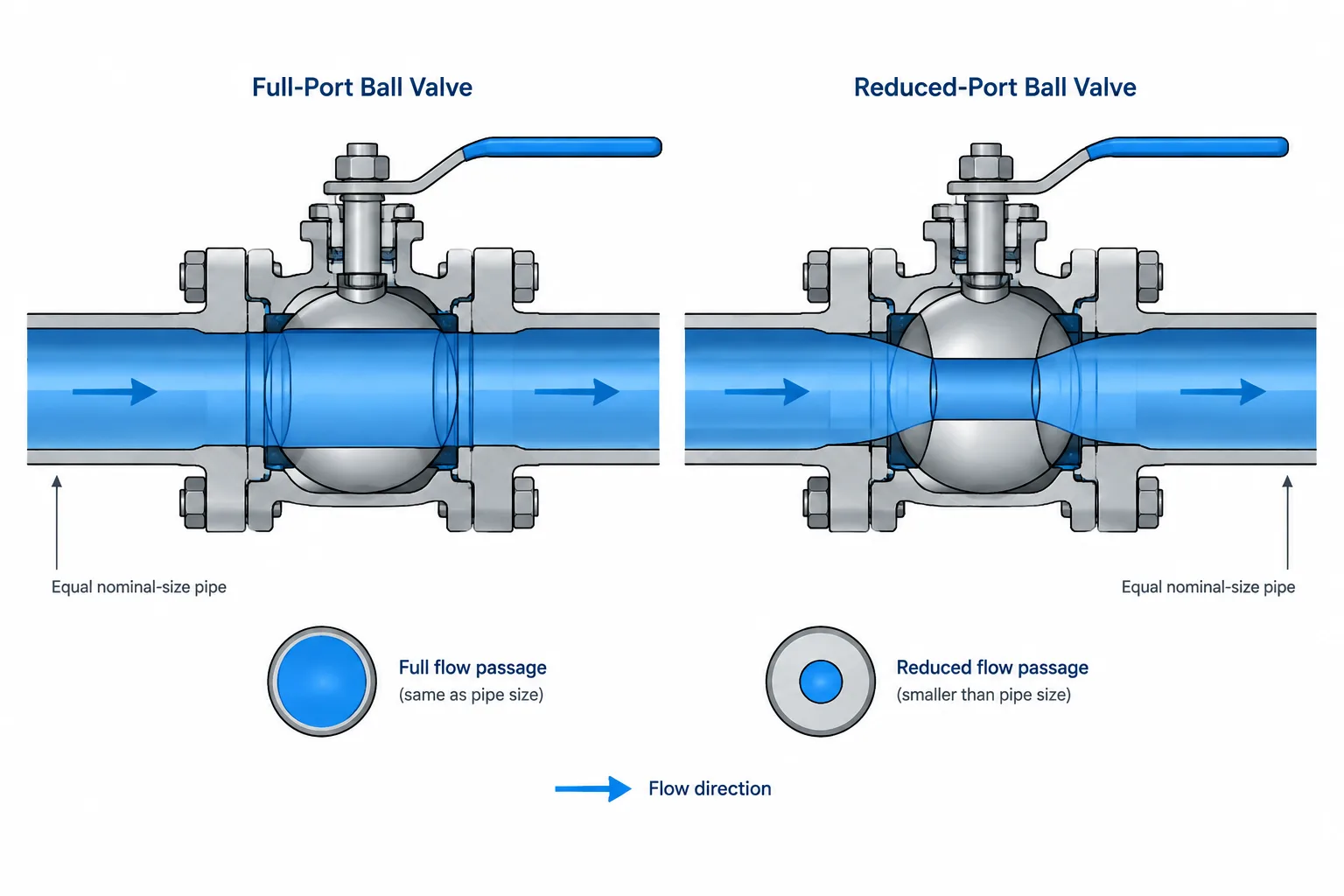
Full-port vs. reduced-port valve selection cannot be resolved from nominal valve size or external CAD geometry alone. The connection designation, internal opening, flow path, and product construction describe different aspects of the valve.
This guide explains how bore terminology relates to hydraulic behavior, pigging, cleanability, replacement decisions, specifications, and CAD documentation. It also identifies which details must be confirmed from controlled project documents and verified product data.
A valve may have the same nominal size and end connections as the adjoining pipe while providing a substantially different internal flow passage. That distinction is commonly described with terms such as full port, full bore, reduced port, and reduced bore.
These terms affect more than hydraulic calculations. Valve bore geometry can influence pigging, draining, solids handling, pressure loss, equipment performance, maintenance, and replacement selection. For piping designers and CAD users, the main challenge is that a valve’s nominal size does not fully describe its internal opening.
Nominal valve size is not the bore diameter
A nominal valve size identifies the general connection size of the valve. It helps match the valve ends to the piping system, but it should not be interpreted as a measured internal diameter.
The actual flow path depends on several variables:
- Valve type and body design
- Port classification
- Pipe wall thickness or schedule at the connection
- Seat, liner, and closure-element geometry
- Manufacturer design
- Applicable valve specification or project piping class
This is similar to the distinction between nominal pipe size and actual pipe inside diameter. Two adjoining components can carry the same nominal size designation while having different internal openings.
What is a full-port valve?
A full-port valve, also called a full-bore valve, has an internal passage intended to provide a relatively open path through the valve. In a ball valve, for example, this generally means the hole through the ball is designed to align closely with the connected flow passage when the valve is fully open.
“Full port” should not automatically be read as “exactly equal to the pipe inside diameter.” Pipe inside diameter changes with wall thickness, while valve designs are manufactured around their own dimensional criteria. The actual relationship must be checked using verified valve data.

A full-port arrangement may be important where the system requires:
- Passage of cleaning pigs or inspection tools
- Lower restriction through an open isolation valve
- Reduced locations for solids or debris to collect
- A smoother internal transition
- Drainability or cleanability
- Consistency with process or equipment requirements
Even when a valve is described as full port, other internal features may still affect pig passage or cleanability. Seat geometry, body cavities, end transitions, and adjacent welds must also be considered.
What is a reduced-port valve?
A reduced-port valve has a flow opening smaller than the passage associated with its nominal end size. The body ends may connect directly to the specified pipe size, but the internal path narrows through the valve.
This configuration can make the valve more compact or economical for some services. It may be acceptable where the resulting restriction is included in the hydraulic design and where unrestricted passage is not required.
A reduced opening can introduce practical concerns:
- Additional pressure loss
- Higher local velocity through the restricted section
- Potential collection points for solids
- Incompatibility with some pigging operations
- A step in the internal flow path
- Different erosion, noise, or cavitation considerations depending on service
These effects cannot be evaluated from the CAD body envelope alone. Process calculations and manufacturer data are needed where bore geometry is significant.
Full port and reduced port are not universal dimensions
Port terminology is useful, but it does not replace a dimensional definition. Different valve types and product designs may use the terms differently. Labels such as “standard port” can be especially ambiguous unless the associated specification or manufacturer explains what they mean.
| Term | General meaning | What still requires verification |
|---|---|---|
| Full port or full bore | A relatively open passage intended to approach the connected flow path | Actual bore, transitions, seat geometry, and piggability |
| Reduced port or reduced bore | An internal opening smaller than the nominal connection passage | Minimum opening, pressure-loss data, and service suitability |
| Standard port | A product-family term that may indicate a commonly supplied bore arrangement | The manufacturer’s precise definition |
| Nominal size | The designated connection size | Actual end bore and internal valve passage |
If minimum bore matters, the design documents should state the required characteristic clearly rather than relying only on informal terminology.
Valve type changes the meaning of the flow path
Port classification is most visibly associated with ball valves, but internal restriction also matters in other valve types. A gate valve may provide a comparatively straight path when fully open, while globe-style flow paths intentionally change direction through the body. Butterfly valves retain a disc and shaft within the passage even when open. Check valves may have hinges, discs, guides, or other internal elements affecting the available opening.
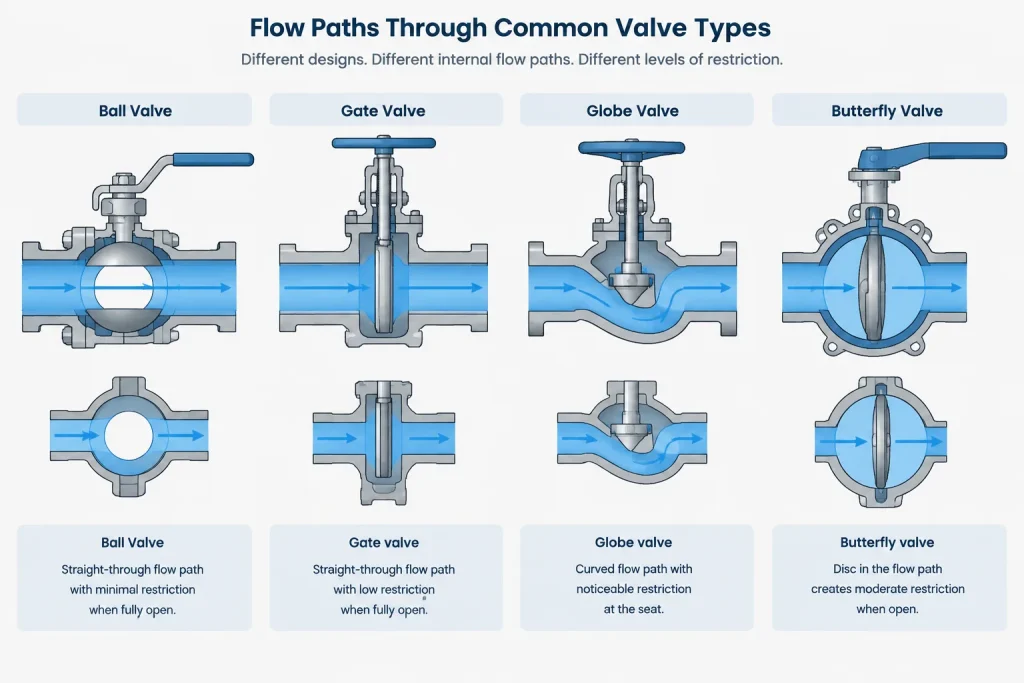
For this reason, comparing valves only by a nominal bore label can be misleading. Flow resistance depends on the complete internal geometry, not solely on one measured opening. Hydraulic calculations should use appropriate verified loss information rather than an assumed bore category.
When bore geometry becomes a design requirement
Pigged pipelines
A piggable line needs a continuous path compatible with the selected pig or inspection tool. A full-port label is a starting point, not final confirmation. Designers should review the minimum internal passage, seat transitions, adjacent fittings, branch openings, and any changes in wall thickness.
Slurries and solids-bearing services
Internal steps and body cavities may trap material or accelerate localized wear. Valve orientation and body design can matter as much as the nominal port classification.
Sanitary or cleanable systems
A large opening does not necessarily mean the valve is drainable or free of retention areas. Cleanability must be evaluated from the complete internal construction and installation orientation.
Hydraulic-sensitive systems
A restriction can affect available pressure at downstream equipment or change pump-system behavior. The process or hydraulic discipline should determine whether the valve loss is acceptable.
Replacement and maintenance
A replacement valve can match size, pressure designation, end connection, and face-to-face length yet still have a different bore. Port requirements should therefore be included in requisitions and replacement checks when they are operationally important.
How to represent valve bore information in CAD
Most plant models use simplified external valve geometry. This is usually appropriate because the model’s primary purposes are layout, connection control, interference review, access planning, and drawing production. Modeling every internal seat and port would add complexity without helping most coordination tasks.
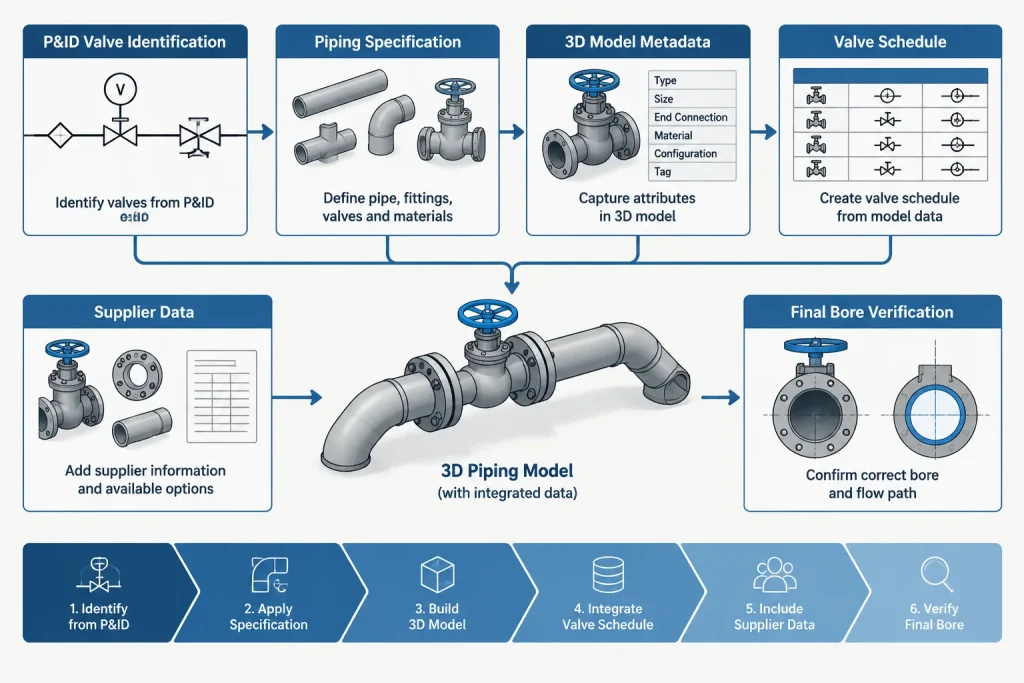
However, simplified geometry should not cause important bore information to disappear. A practical CAD object or project database may carry:
- Valve tag
- Nominal size
- Valve type
- End-connection type
- Port classification
- Verified minimum bore when required
- Flow direction if the valve design is directional
- Manufacturer and model information after selection
- Pigging or cleanability requirement where applicable
The external model should use verified face-to-face, end, operator, and maintenance-envelope dimensions. A generic CAD block may support early layout, but it should not be treated as proof of the internal bore or final product suitability.
P&ID, model, and specification responsibilities
A P&ID may identify the valve function and type without graphically distinguishing full port from reduced port. If port geometry is important, the requirement may instead be controlled by the valve specification, piping material class, line list, process notes, valve data sheet, or purchase description.
The 3D model should remain consistent with those documents. Designers should avoid adding an unsupported full-port attribute merely because a catalog symbol or CAD family uses that description by default.
A sound workflow is to separate three questions:
- Process requirement: Is unrestricted passage, pigging, cleanability, or a specific hydraulic performance required?
- Specification requirement: What valve construction and port description are permitted by the project documents?
- Selected-product verification: Does the actual valve provide the required bore, dimensions, materials, and operating characteristics?
CAD and design review checklist
- Do not infer valve bore from nominal size alone.
- Confirm whether “full port,” “reduced port,” or “standard port” is defined by the project or supplier.
- Check the actual minimum passage where pigging or tool passage is required.
- Coordinate valve bore with the pipe inside diameter and adjacent component transitions.
- Use verified hydraulic data where valve pressure loss affects system performance.
- Preserve port classification in valve schedules, tags, databases, and procurement records.
- Verify that replacement valves match the required bore, not only the connection size and face-to-face length.
- Treat generic CAD components as layout resources rather than evidence of product compliance.
The practical takeaway
The difference between full-port and reduced-port valves is an internal geometry issue that can have system-wide consequences. Nominal size establishes the connection designation, but it does not establish the actual flow opening. Where bore geometry affects operation, the requirement must be stated, carried through the piping data, and verified against the selected valve.
For CAD users, the best approach is usually to model the verified external envelope while maintaining bore-related information as controlled component data. That keeps the model efficient without losing a requirement that may be critical to flow, cleaning, pigging, or future replacement.
Closing the documentation gap
Bore-related mistakes often occur when information passes between process engineering, piping design, procurement, suppliers, and maintenance. One discipline may treat full port as a functional requirement while another treats it as a catalog description. The requirement can be lost if it is not carried in a controlled data field or specification.
A useful documentation approach distinguishes between required performance and selected-product data. The requirement states what the system needs, such as compatible tool passage, acceptable hydraulic performance, drainability, or solids handling. Product data records how the chosen valve satisfies that requirement.
Information to establish during design
- The operating reason bore geometry matters
- Whether the requirement applies to every valve in the line or only selected locations
- The project document that controls the port classification
- Whether an actual minimum passage must be verified
- Which discipline approves hydraulic, pigging, cleaning, or maintenance suitability
Information to confirm after product selection
- The supplier’s definition of the stated port terminology
- The verified internal passage and transition geometry where relevant
- Compatibility with the specified ends and adjoining components
- External dimensions needed for layout and maintenance access
- Consistency between the valve data sheet, model attributes, schedule, and purchasing records
This separation prevents a generic model label from becoming an unintended engineering assumption. It also gives maintenance and procurement teams a clearer basis for evaluating future replacements.
Frequently asked questions
Does full port mean the valve bore equals the pipe inside diameter?
Not automatically. Pipe inside diameter varies with wall thickness, and valve manufacturers use product-specific internal geometry. The actual bore and transitions must be checked when equality or minimum passage is important.
Can nominal valve size identify the flow opening?
No. Nominal size identifies the general connection designation. It does not, by itself, define the valve’s measured internal opening.
Is a reduced-port valve always unsuitable?
No. It may be acceptable when its restriction is included in the system design and the service does not require unrestricted passage. Suitability depends on the process, hydraulic, maintenance, and operating requirements.
Can a generic CAD valve block confirm that a valve is full port?
No. Generic blocks normally represent the external arrangement needed for layout and drawing production. Port classification and verified bore data must come from controlled specifications or selected-product documentation.
Should port classification appear on the P&ID?
That depends on the project’s documentation practice. The requirement may instead be controlled through a piping class, valve specification, line list, data sheet, schedule, note, or purchase description. The important point is that the requirement remains traceable.
What should be checked when replacing an existing valve?
Connection size and external fit are not enough. Review the required port classification, internal passage, valve type, end connections, materials, operating characteristics, and other controlled project requirements before approving a substitute.