Author: draftsman

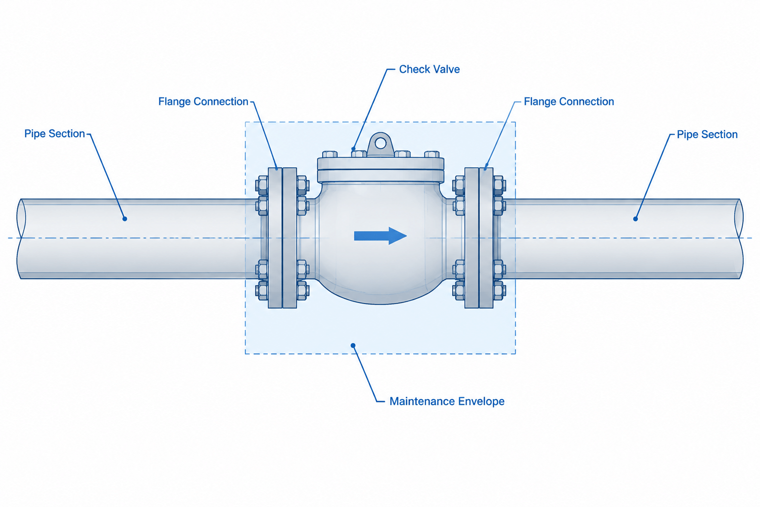
  • Check Valve Types in Piping CAD: Flow Direction, Orientation, and Maintenance

    Check Valve Types in Piping CAD: Flow Direction, Orientation, and Maintenance

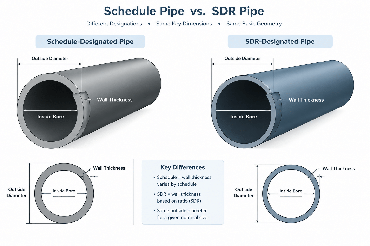
  • Pipe Schedule vs. SDR: How the Two Wall-Thickness Systems Differ

    Pipe Schedule vs. SDR: How the Two Wall-Thickness Systems Differ

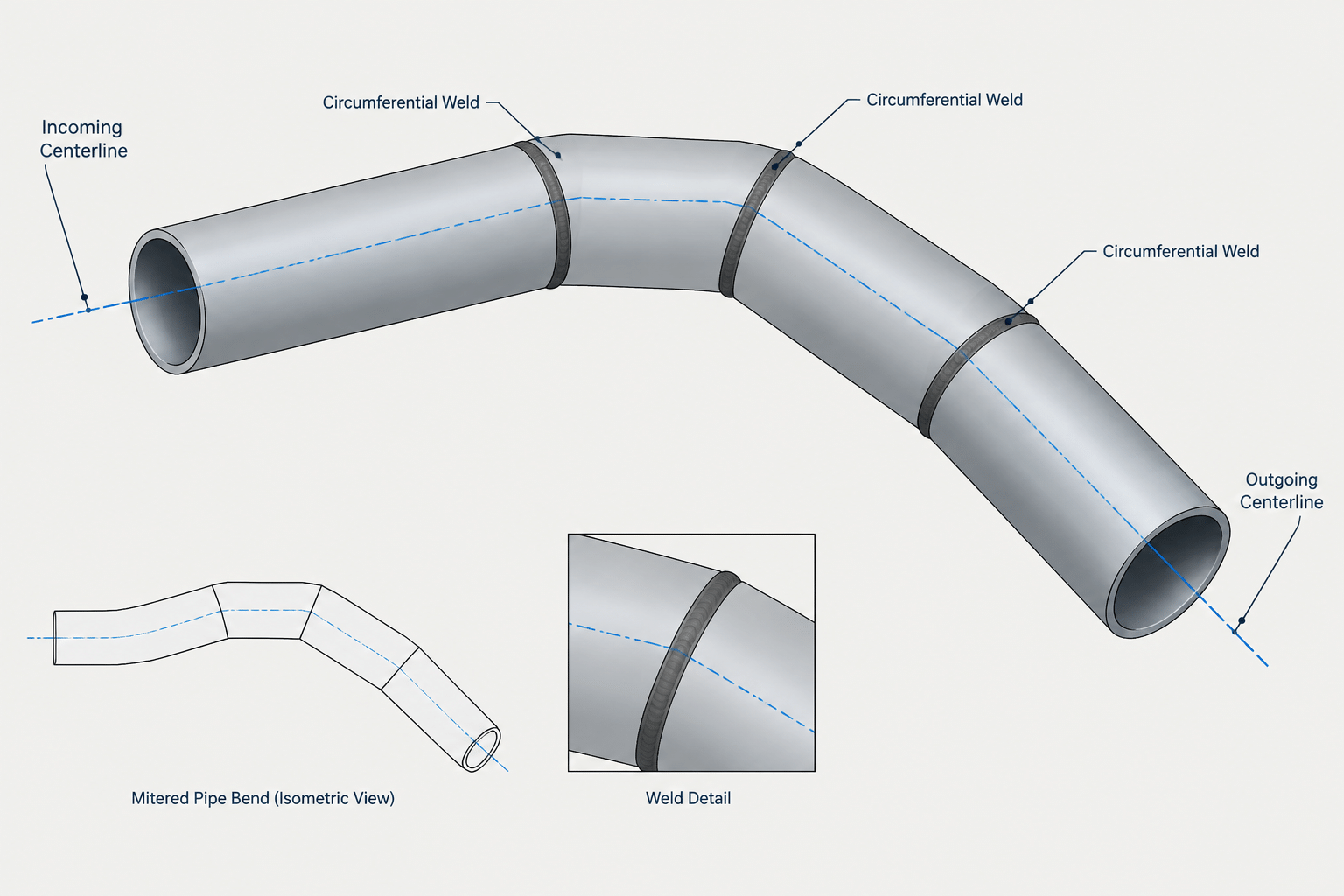
  • Mitered Pipe Bends in CAD: Segment Geometry, Weld Layout, and Fabrication Documentation

    Mitered Pipe Bends in CAD: Segment Geometry, Weld Layout, and Fabrication Documentation

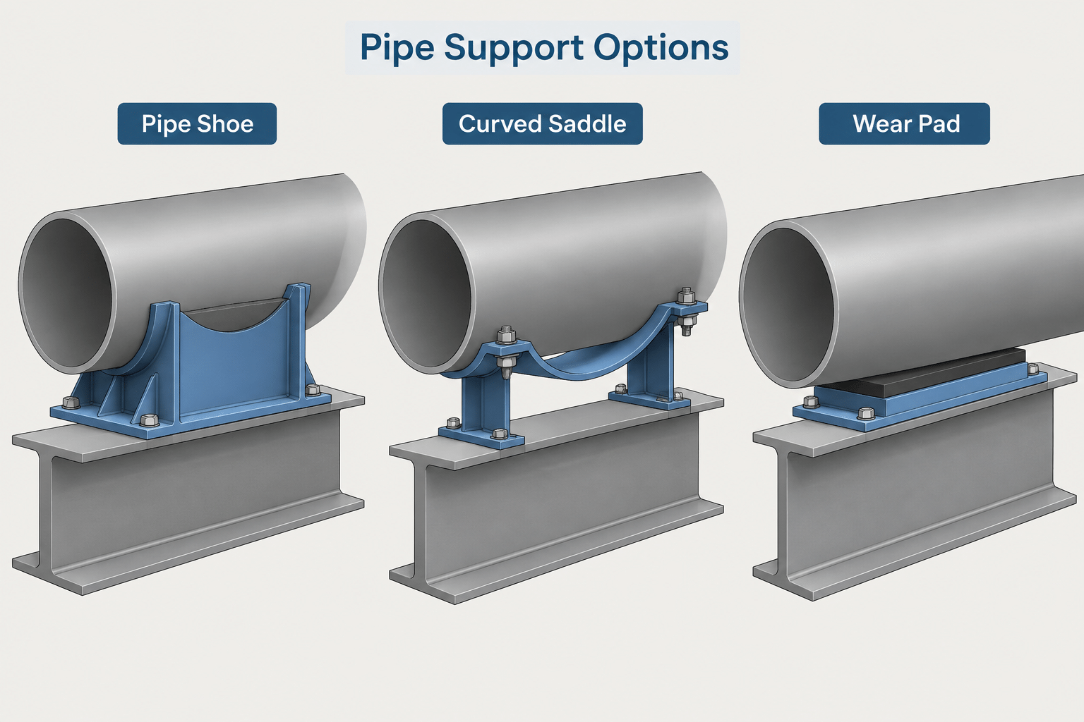
  • Pipe Shoes, Saddles, and Wear Pads in CAD: Geometry, Contact, and Documentation

    Pipe Shoes, Saddles, and Wear Pads in CAD: Geometry, Contact, and Documentation

  • Piping CAD Model Levels of Detail: Matching Geometry to Design Purpose

    Piping CAD Model Levels of Detail: Matching Geometry to Design Purpose

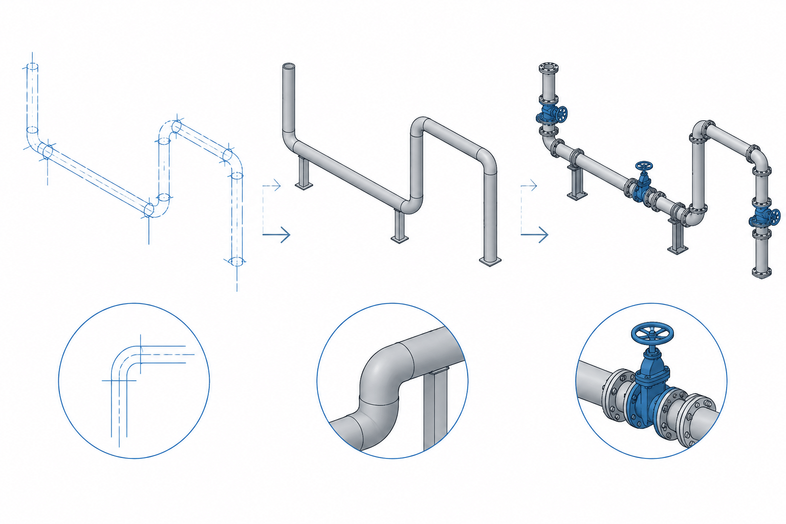
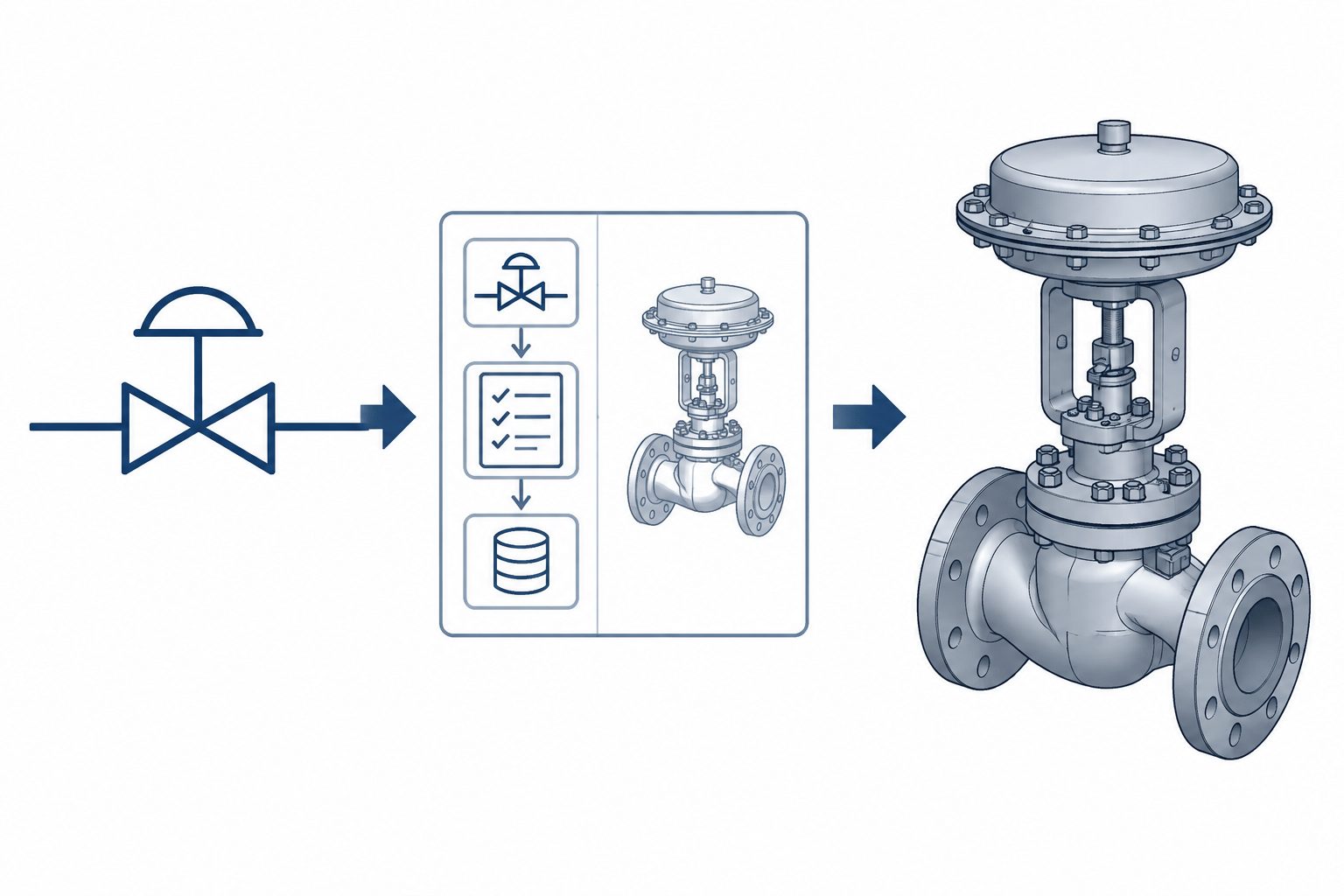
  • P&ID Symbols vs. 3D Piping Components: How to Translate Process Intent into CAD

    P&ID Symbols vs. 3D Piping Components: How to Translate Process Intent into CAD

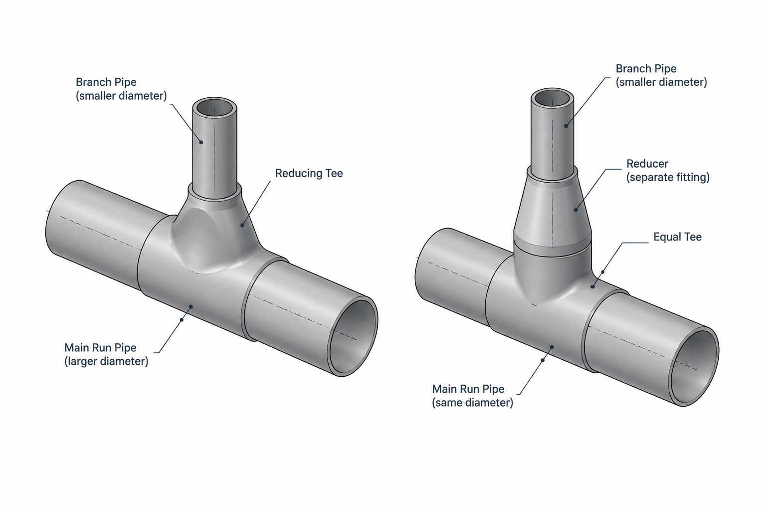
  • Reducing Tee vs. Equal Tee and Reducer: A Practical Piping Layout Comparison

    Reducing Tee vs. Equal Tee and Reducer: A Practical Piping Layout Comparison

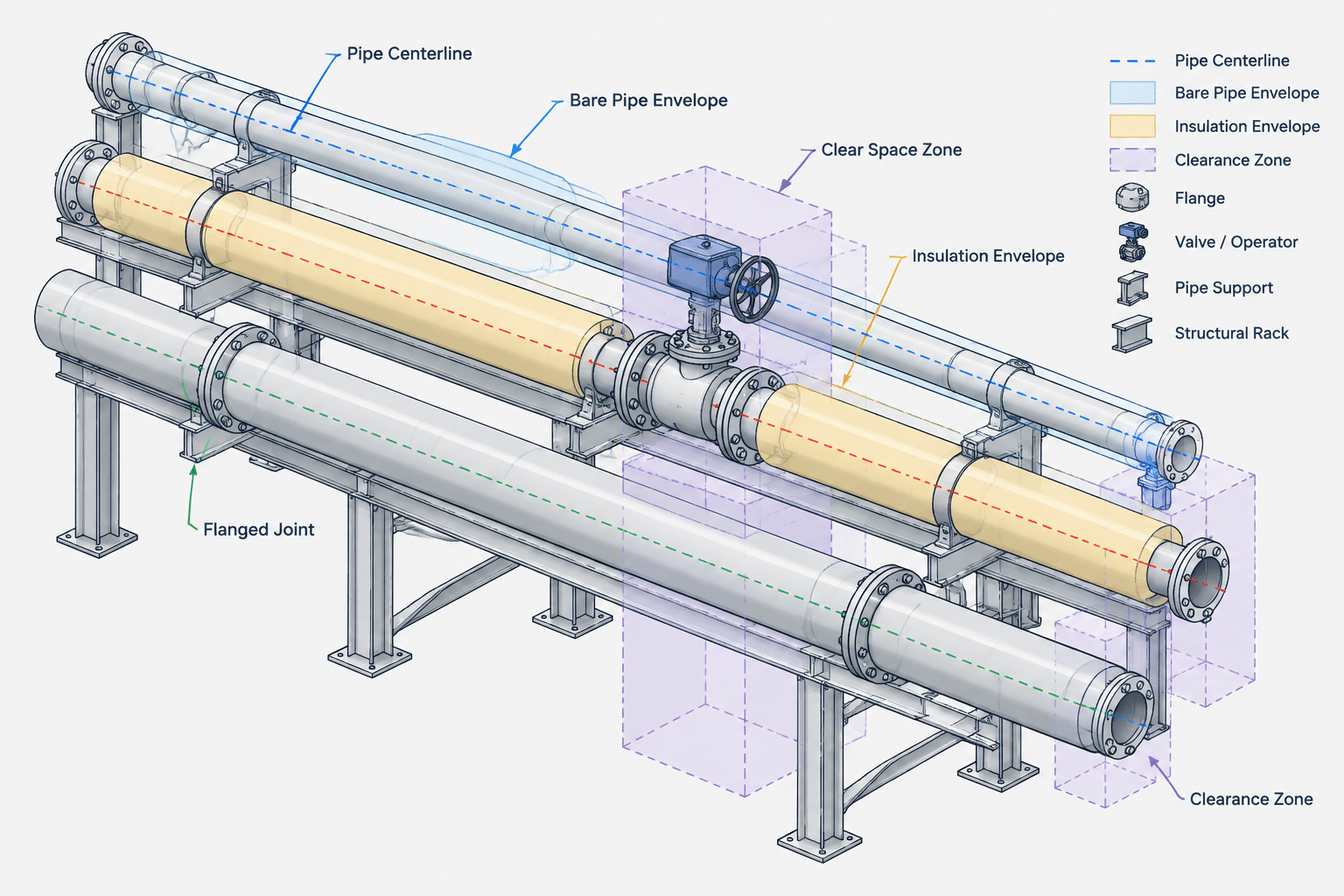
  • Pipe Centerline Spacing in CAD: How to Account for Insulation, Flanges, Valves, and Access

    Pipe Centerline Spacing in CAD: How to Account for Insulation, Flanges, Valves, and Access

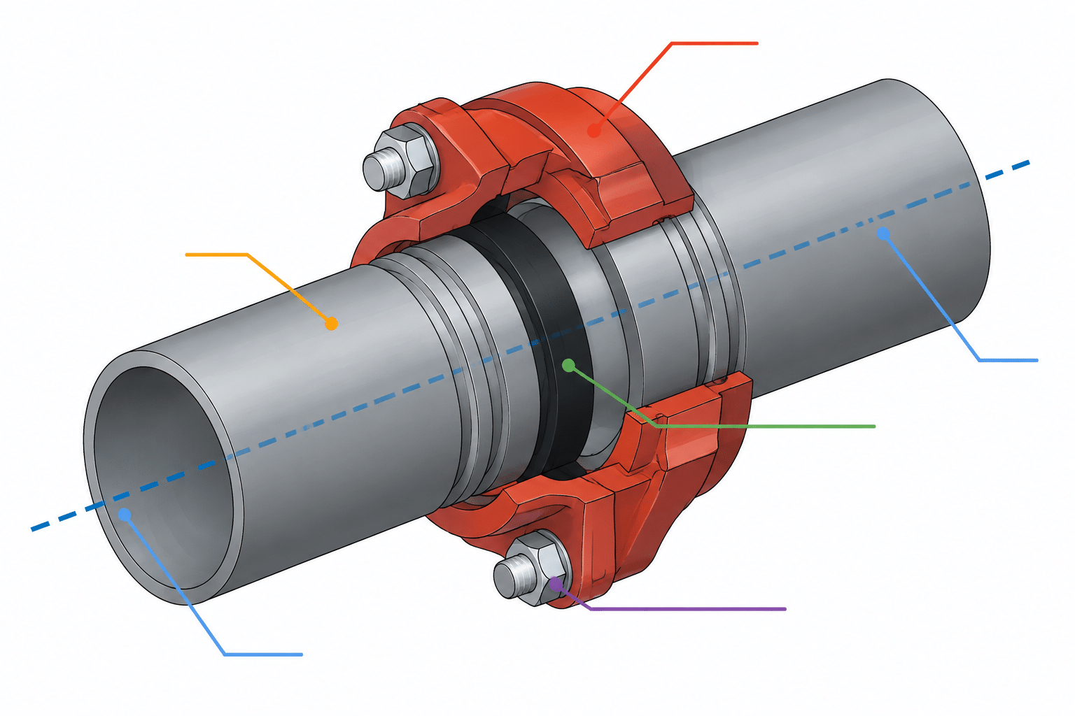
  • Grooved Pipe Connections in CAD: Couplings, End Gaps, and Cut-Length Control

    Grooved Pipe Connections in CAD: Couplings, End Gaps, and Cut-Length Control