Category: How To

  • Socket-Weld Piping in CAD: Insertion Depth, Assembly Gap, and Cut-Length Control

    Socket-Weld Piping in CAD: Insertion Depth, Assembly Gap, and Cut-Length Control

  • Piping Spool Breaks in CAD: Planning Fabrication, Transport, and Field Assembly

    Piping Spool Breaks in CAD: Planning Fabrication, Transport, and Field Assembly

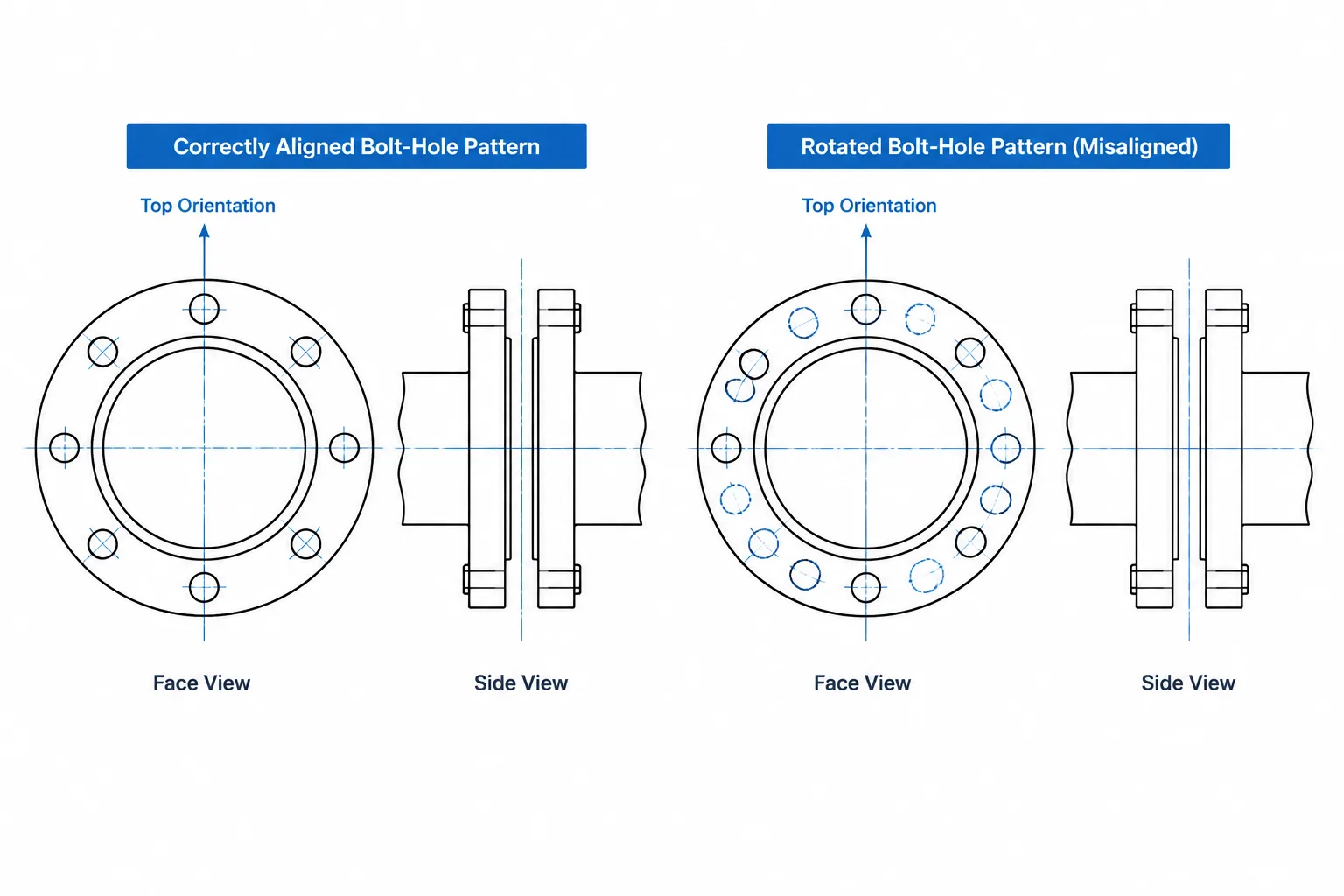
  • Flange Bolt Length in CAD: How to Build and Check the Joint Stack-Up

    Flange Bolt Length in CAD: How to Build and Check the Joint Stack-Up

  • Piping Component Insertion Points in CAD: Origins, Ports, and Replacement-Safe Modeling

    Piping Component Insertion Points in CAD: Origins, Ports, and Replacement-Safe Modeling

  • As-Built Piping Drawings in CAD: A Field Verification and Update Workflow

    As-Built Piping Drawings in CAD: A Field Verification and Update Workflow

  • Single-Line, Double-Line, and 3D Piping Drawings: Choosing the Right CAD Representation

    Single-Line, Double-Line, and 3D Piping Drawings: Choosing the Right CAD Representation

  • Cold Position vs. Hot Position in Piping CAD: How to Document Thermal Movement Clearly

    Cold Position vs. Hot Position in Piping CAD: How to Document Thermal Movement Clearly

  • Pipe Weld End Preparation in CAD: Bevels, Root Gaps, and Cut-Length Control

    Pipe Weld End Preparation in CAD: Bevels, Root Gaps, and Cut-Length Control

  • Pipe Bends vs. Elbows in CAD: Geometry, Tangent Points, and Documentation

    Pipe Bends vs. Elbows in CAD: Geometry, Tangent Points, and Documentation