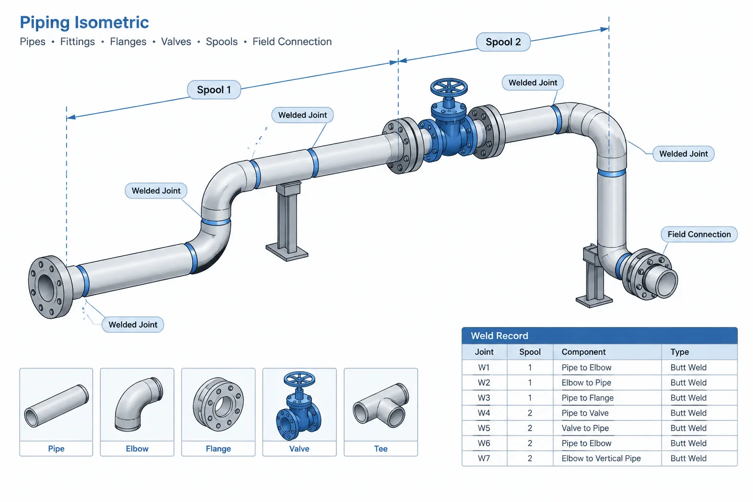
Piping weld maps in CAD are not merely annotated drawings. They form the visual part of a traceability system that connects each tracked joint with fabrication, inspection, installation, and turnover records.
This guide explains how to keep that connection reliable when assigning joint identifiers, defining spool boundaries, coordinating CAD data, and processing revisions or field changes. It is intended for designers, drafters, fabricators, inspectors, and document-control personnel who need to interpret or maintain weld-map information without confusing drawing annotation with the governing quality record.
A piping weld map connects drawing geometry with the records created during fabrication, inspection, testing, and installation. It identifies where individual welded joints are located and gives each tracked joint a stable reference that can be used across isometrics, spool drawings, weld logs, inspection reports, and turnover documentation.
The map may be incorporated into a fabrication isometric, issued as an annotated copy of another drawing, or generated as a separate report linked to the piping model. Its format varies by project, but its purpose remains consistent: a reviewer should be able to take a weld record and locate the corresponding physical joint without relying on an informal description.
A useful weld map does more than place bubbles beside weld symbols. Its identifiers, geometry, and associated data must remain coordinated as spools are split, joints move from the shop to the field, and design revisions alter the piping assembly.
What a piping weld map controls
A weld map generally shows the location and identity of welds selected for project tracking. The drawing may distinguish between shop welds, field welds, tie-in welds, and other project-defined categories. The governing construction documents and quality procedures determine which joints must be included and what information must be recorded.
The map itself is primarily a location and identification document. Detailed fabrication and quality information may remain in linked records rather than being printed beside every joint. Depending on the project workflow, those records can include:
- Weld or joint identification number
- Line number and spool number
- Joint category or weld configuration
- Shop, field, or tie-in designation
- Connected component or piece-mark references
- Welder identification recorded by the fabrication organization
- Inspection or examination record references
- Repair status and related record identifiers
- Completion, acceptance, or turnover status
A CAD drawing should not independently assign inspection acceptance criteria or weld requirements. Those requirements come from the applicable design documents, welding procedures, quality plan, and project specifications. The drawing provides a reliable spatial reference for the resulting records.
Weld number, spool number, and piece mark are different identifiers
Several identifiers can appear near the same joint, but they do not control the same item. Confusing them creates ambiguous fabrication and turnover records.
| Identifier | What it identifies | Typical use |
|---|---|---|
| Line number | A piping system or defined line segment | Connects the joint to service and piping-class information |
| Spool number | A prefabricated piping assembly | Supports fabrication, shipping, erection, and status tracking |
| Piece mark | An individual pipe piece, fitting, support item, or assembly item | Connects drawing items to fabrication and material records |
| Weld number | A specific tracked welded joint | Links the physical joint to welding and inspection records |
| Drawing number | The controlled document containing the representation | Provides document-level revision and issue control |
A weld number should identify the joint, not merely the symbol or text object placed in CAD. If a label is moved for clarity, the joint identity must remain unchanged. If a joint is deleted or replaced by a substantially different connection, the project’s numbering and revision procedure should determine whether its identifier is retired, reassigned, or superseded.
Building a stable joint-numbering system
There is no universal numbering format that fits every piping project. A small fabrication package may use sequential joint numbers within each isometric, while a larger data-driven project may construct identifiers from line, spool, area, or document fields. Whatever method is selected, it should be unique within its stated scope and remain understandable after drawing revisions.
Define the uniqueness boundary
A number such as “Weld A” is meaningful only when the user knows whether it is unique within a spool, an isometric, a line, or the entire project. The identifier displayed on a crowded drawing can be shortened, but the database or weld log should retain enough context to distinguish it from similarly labeled joints elsewhere.
Avoid encoding unstable information
Identifiers become difficult to maintain when every character describes a condition that may change. For example, embedding shop or field status directly in the permanent joint number can create a conflict when the fabrication plan changes. It is often more manageable to store status or category as a separate attribute while keeping the core joint identifier stable.
Do not silently reuse deleted numbers
Reusing a former weld number can cause older inspection reports or marked-up drawings to point to the wrong joint. When practical, preserve a record that the original joint was deleted, replaced, or superseded. The exact retention method should follow the project’s document-control procedure.
Locating welds clearly on piping drawings
The weld callout should point to an unambiguous joint location. On an isometric, this is usually the connection between two represented components or between a pipe segment and a component end. Leaders should not terminate in open space where they could be interpreted as referring to either of two nearby joints.
Special attention is needed in congested locations:
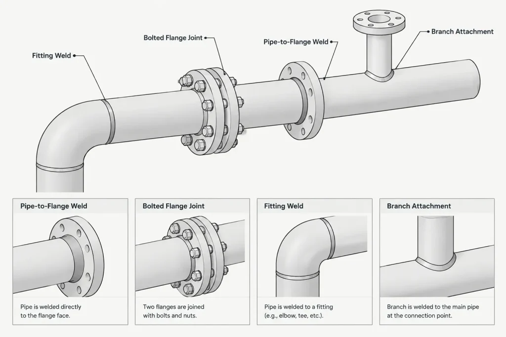
- Flanged assemblies: Distinguish the pipe-to-flange weld from the bolted flange joint. A gasket line is not a weld location.
- Branch connections: Make clear whether the identifier refers to the complete branch attachment or to separately tracked weld portions under the project procedure.
- Socket-weld components: Point to the welded component end rather than implying that the joint is at the internal pipe stop.
- Reducers and fittings: Place the callout at the correct end when different joints are close together.
- Continuation points: Avoid placing a joint bubble at a drawing break unless an actual weld or field connection exists there.
- Closely spaced field joints: Use offset leaders or a local detail instead of stacking unreadable labels.
The graphical location should also agree with the bill of material and spool definition. A weld shown inside one spool cannot simultaneously be treated as the field joint between two separate spools without an intentional revision to the fabrication plan.
Shop welds, field welds, and tie-ins
Shop and field classifications describe where the joint is intended to be made, not its weld process or acceptance status. A shop weld is generally completed under fabrication-shop conditions. A field weld is planned for installation or assembly at the site. A tie-in weld connects new work to an existing system or to another defined construction boundary.
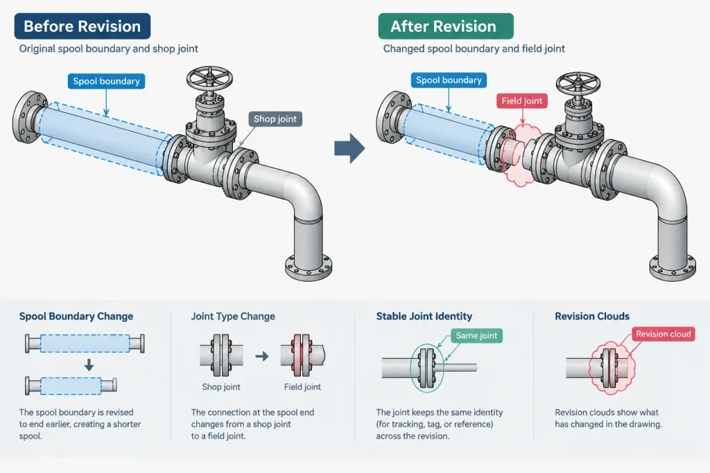
These classifications affect spool planning, shipping geometry, access, field fit-up, and the division of responsibility between organizations. They can change during constructability review. A large spool may be divided for transportation, creating a new field joint, or a planned field weld may be moved to improve access.
When this happens, the CAD team should update more than the graphic weld symbol. The spool break, piece marks, material list, weld data, isometric notes, and associated status records may all be affected. A model change that is not propagated to fabrication records can leave two conflicting definitions of the same assembly.
Using CAD attributes and model data
In a data-rich workflow, a weld location can be represented by an object or relationship with attached properties. Useful fields may include the joint identifier, line number, connected item identifiers, fabrication category, drawing reference, and lifecycle status. The displayed bubble can then read selected properties rather than existing as unrelated text.
This approach supports consistency, but it does not eliminate checking. Automated weld generation may create unwanted records at modeling splits, software connectors, or drawing continuation points. It may also miss a joint represented only by drafting geometry. Designers should verify that each generated record corresponds to a physical joint intended for tracking.
For basic two-dimensional CAD, attributed blocks can provide similar discipline. Use a consistent insertion convention, place the block close to the applicable joint, and keep the leader endpoint separate from the text location. If data are exported to a spreadsheet or database, include a persistent object key or another controlled method for reconnecting the record to the drawing object.
Revision and field-change workflow
Weld maps often continue to develop after the design drawing is issued. Fabricators may adjust spool divisions, field personnel may relocate a joint, and an installed weld may require repair documentation. A controlled workflow should distinguish a design revision from a fabrication-status update.
Before revising a map, review whether the affected joint has already been fabricated, inspected, or included in a turnover package. Changing its number after records exist can break traceability. Where a joint must be relocated or replaced, record the relationship between the former and current condition rather than overwriting history without explanation.
Field markups should state what changed physically. “Weld moved” is incomplete unless the revised location can be established from dimensions, coordinates, connected piece marks, or a clear sketch. The final as-built update should reconcile the drawing, weld log, spool records, and accepted field documentation.
Practical weld-map QA checklist
- Confirm that every displayed weld identifier is unique within the declared numbering scope.
- Verify that each leader points to one physical joint.
- Compare shop and field designations with current spool breaks.
- Check that flange-to-pipe welds are not confused with bolted joints.
- Reconcile joint locations with connected component and piece-mark data.
- Review branch connections and compact assemblies for missing or duplicate identifiers.
- Confirm that deleted joints are handled according to revision procedures.
- Compare the drawing against the weld log or exported joint report.
- Check that field changes have been incorporated into the controlled record.
- Ensure that inspection status is referenced without presenting the CAD map as the acceptance record itself.
A map is useful only when its references remain connected
The value of a piping weld map is not the number of bubbles placed on an isometric. Its value is the dependable link between the joint shown in CAD and the fabrication, welding, inspection, and turnover records associated with that joint.
Stable identifiers, clear leader placement, coordinated spool boundaries, and disciplined revision control make that link durable. Whether the workflow uses a database-driven model or attributed CAD blocks, the central rule is the same: treat the joint as a controlled project record, not as a piece of drawing annotation that can be renumbered or moved without consequence.
From CAD annotation to a controlled project handoff
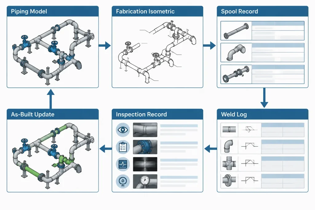
A dependable workflow defines which record controls each type of information. The drawing or model normally provides the joint location, while linked fabrication and quality records carry the applicable welding, inspection, repair, and completion data. The exact division of responsibility should be established by the project rather than assumed by individual CAD users.
Before issuing or revising a weld map, the responsible team should be able to follow the same joint identifier through the drawing, spool information, weld log, inspection references, and field documentation. A mismatch should be resolved at its source instead of being concealed by changing only the visible callout.
Coordination questions for drawing review
- Does the displayed identifier refer to the same physical joint in every connected record?
- Do the spool boundary and shop or field designation describe the current fabrication plan?
- Can the joint be located without depending on an informal field description?
- Are connected piece marks and component references consistent with the represented geometry?
- Has a deleted, relocated, or replaced joint retained an understandable revision history?
- Can exported data be associated with the correct CAD or model object after an update?
Separate geometry changes from status changes
Not every update has the same effect. Moving a callout for readability does not relocate the physical joint. Changing inspection status does not necessarily revise piping geometry. Moving a spool break, changing connected components, or relocating a field joint can affect both the drawing and its linked records.
Classifying the change before editing helps prevent unnecessary renumbering and incomplete updates. When the physical definition changes, review all dependent documents. When only a status field changes, preserve the established joint location and identity unless the project procedure requires otherwise.
Frequently asked questions about piping weld maps
Is a weld map the same as a piping isometric?
No. A piping isometric represents the piping assembly, while a weld map identifies tracked joint locations and connects them with related records. Weld-map information may be placed on an isometric, but the terms do not describe the same function.
What is the difference between a weld symbol and a weld number?
A weld number identifies a tracked physical joint. Welding notation communicates information about the intended connection as directed by the governing design and fabrication documents. Moving a label or symbol for drawing clarity should not change the identity of the joint.
Can the same joint identifier appear on an isometric and a spool drawing?
Yes, when both references represent the same physical joint and the identifier is unique within the project-defined scope. The associated records should make the drawing context clear and prevent confusion with similarly labeled joints elsewhere.
Does every piping connection require a weld number?
Not necessarily. The applicable project specifications, construction documents, and quality procedures determine which joints require tracking. CAD personnel should not create inspection or traceability requirements independently.
Should a weld number change when a shop weld becomes a field weld?
Not automatically. Shop or field classification can be maintained as a separate attribute so the core joint identity remains stable. Any renumbering should follow the project procedure and account for records already issued against the joint.
Is the CAD weld map an inspection acceptance record?
No. It can show or reference inspection information, but acceptance is established through the applicable quality records and procedures. The map provides the spatial connection between those records and the represented joint.