Tag: CAD coordination

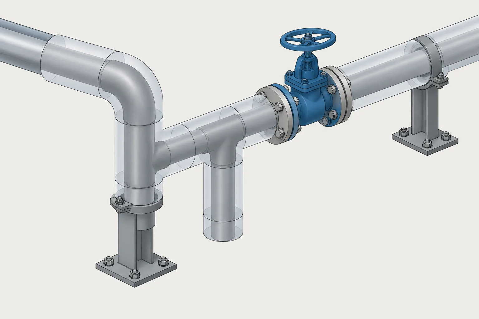
  • Pipe Insulation in CAD: Modeling the Outer Envelope, Thickness Changes, and Removable Covers

    Pipe Insulation in CAD: Modeling the Outer Envelope, Thickness Changes, and Removable Covers

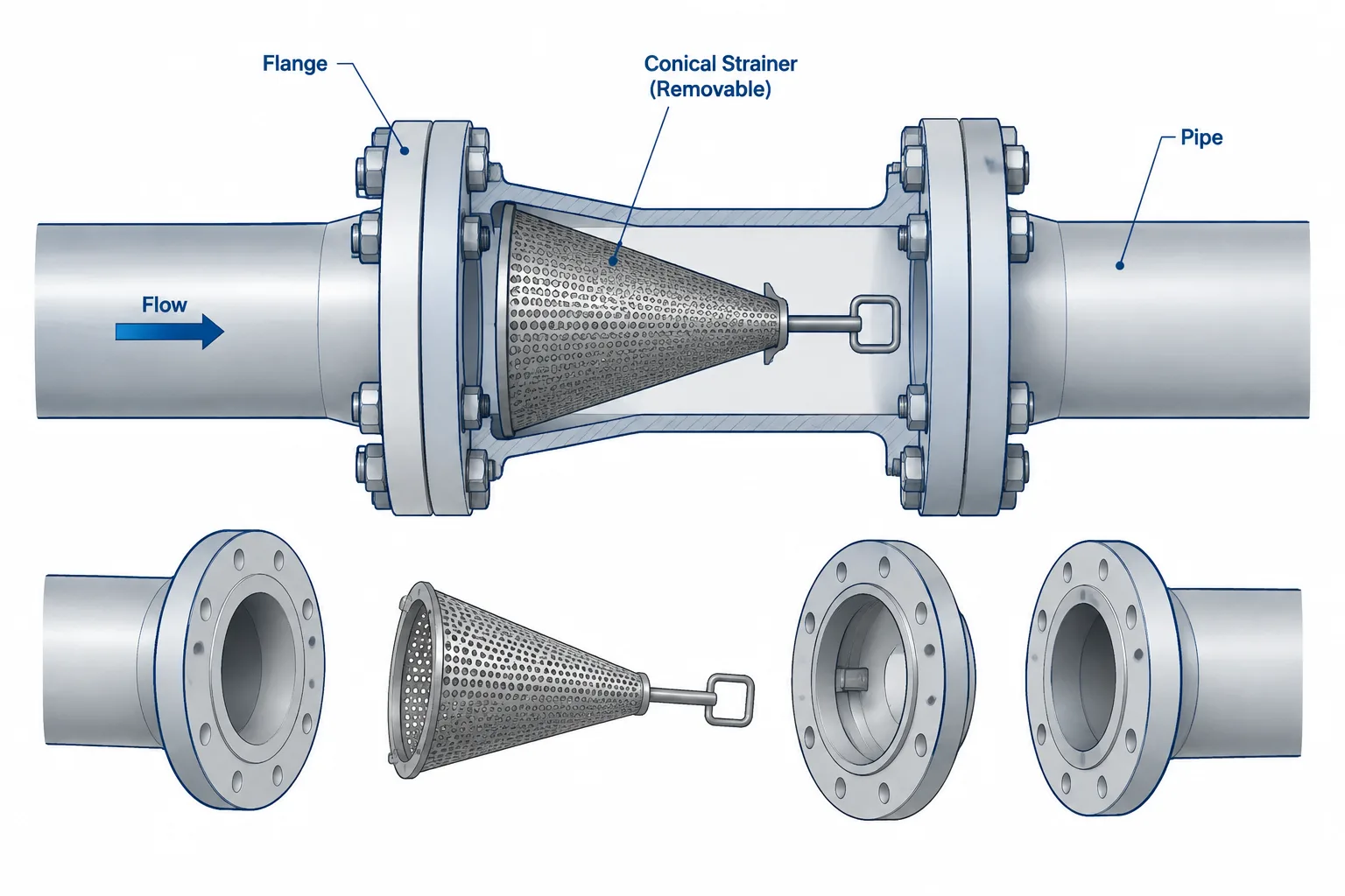
  • Temporary Strainers in Piping CAD: Placement, Orientation, and Removal Planning

    Temporary Strainers in Piping CAD: Placement, Orientation, and Removal Planning

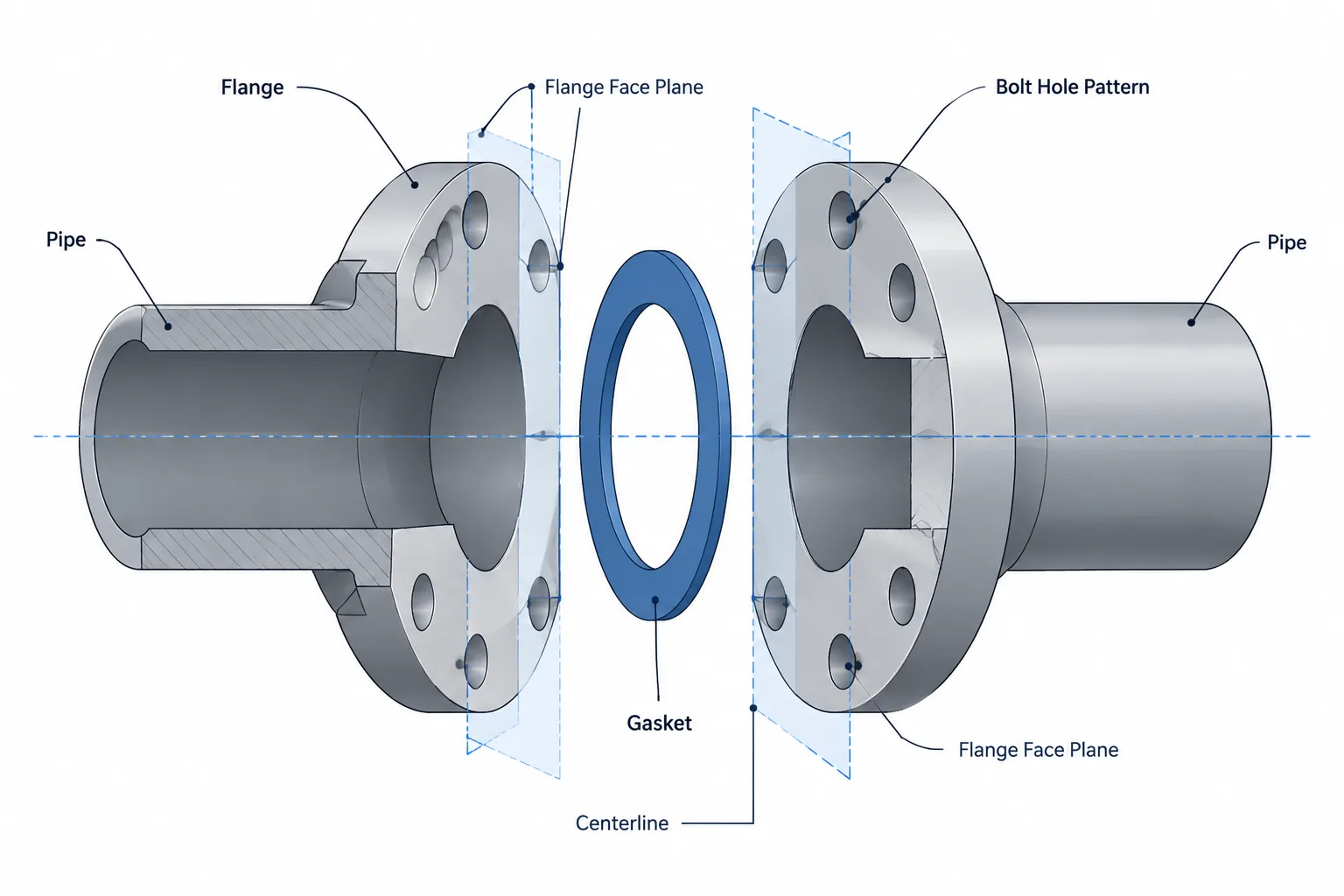
  • Flange Joint Alignment in Piping CAD: Faces, Bores, Bolt Holes, and Field Fit-Up

    Flange Joint Alignment in Piping CAD: Faces, Bores, Bolt Holes, and Field Fit-Up

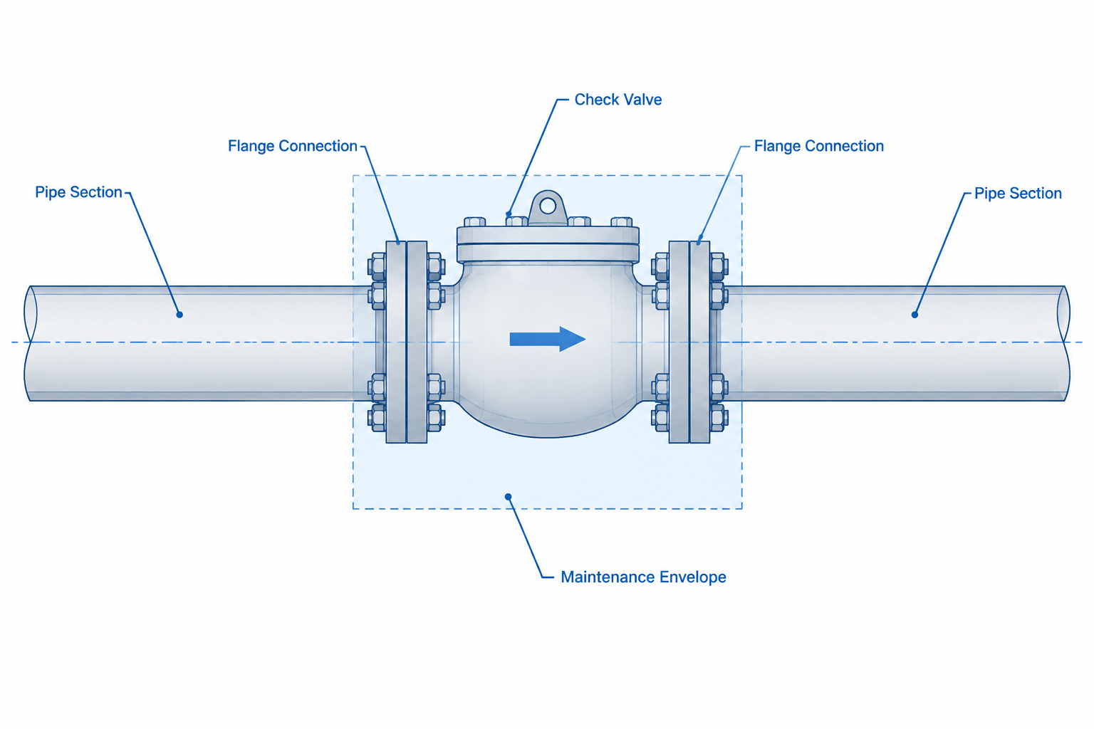
  • Check Valve Types in Piping CAD: Flow Direction, Orientation, and Maintenance

    Check Valve Types in Piping CAD: Flow Direction, Orientation, and Maintenance

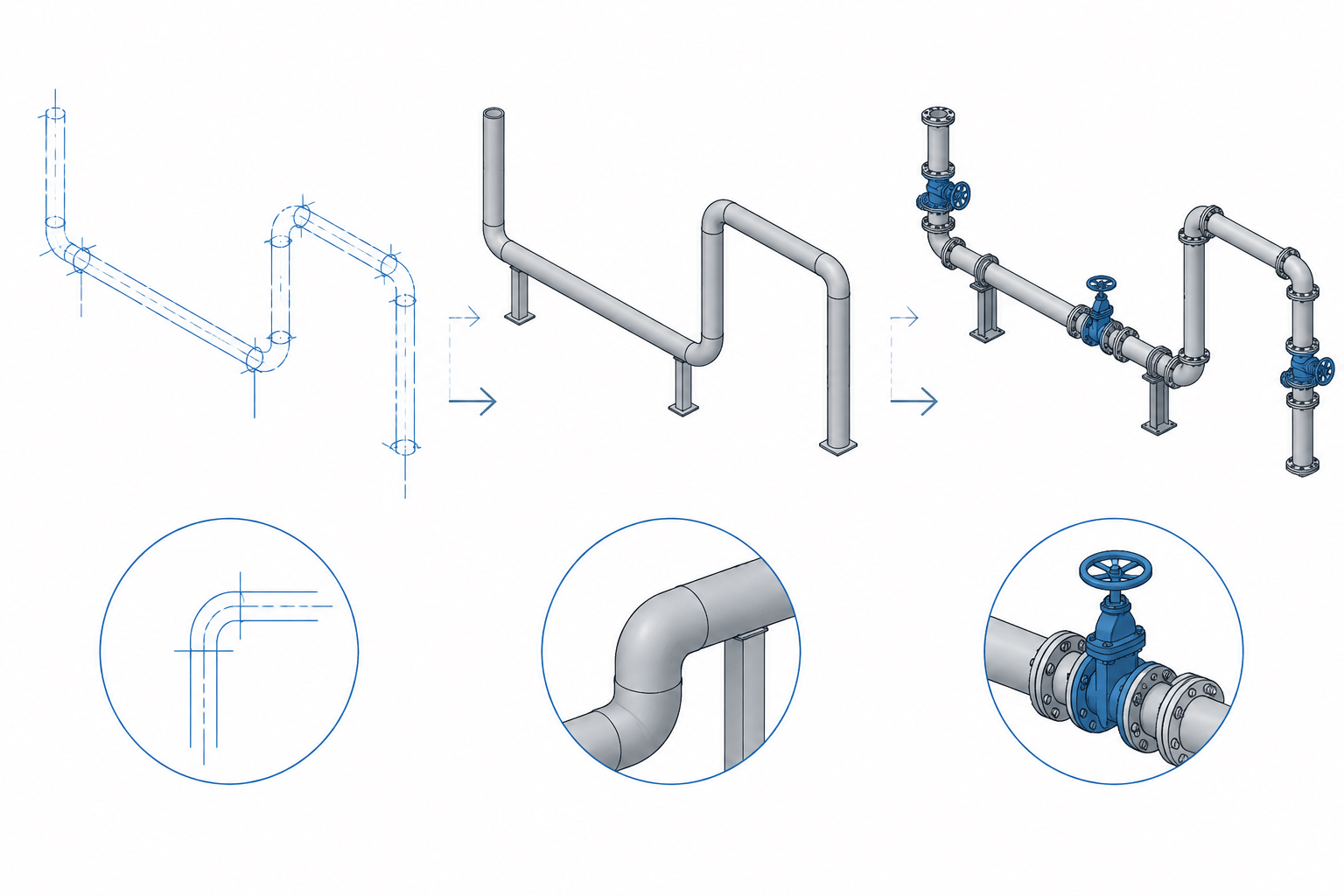
  • Piping CAD Model Levels of Detail: Matching Geometry to Design Purpose

    Piping CAD Model Levels of Detail: Matching Geometry to Design Purpose

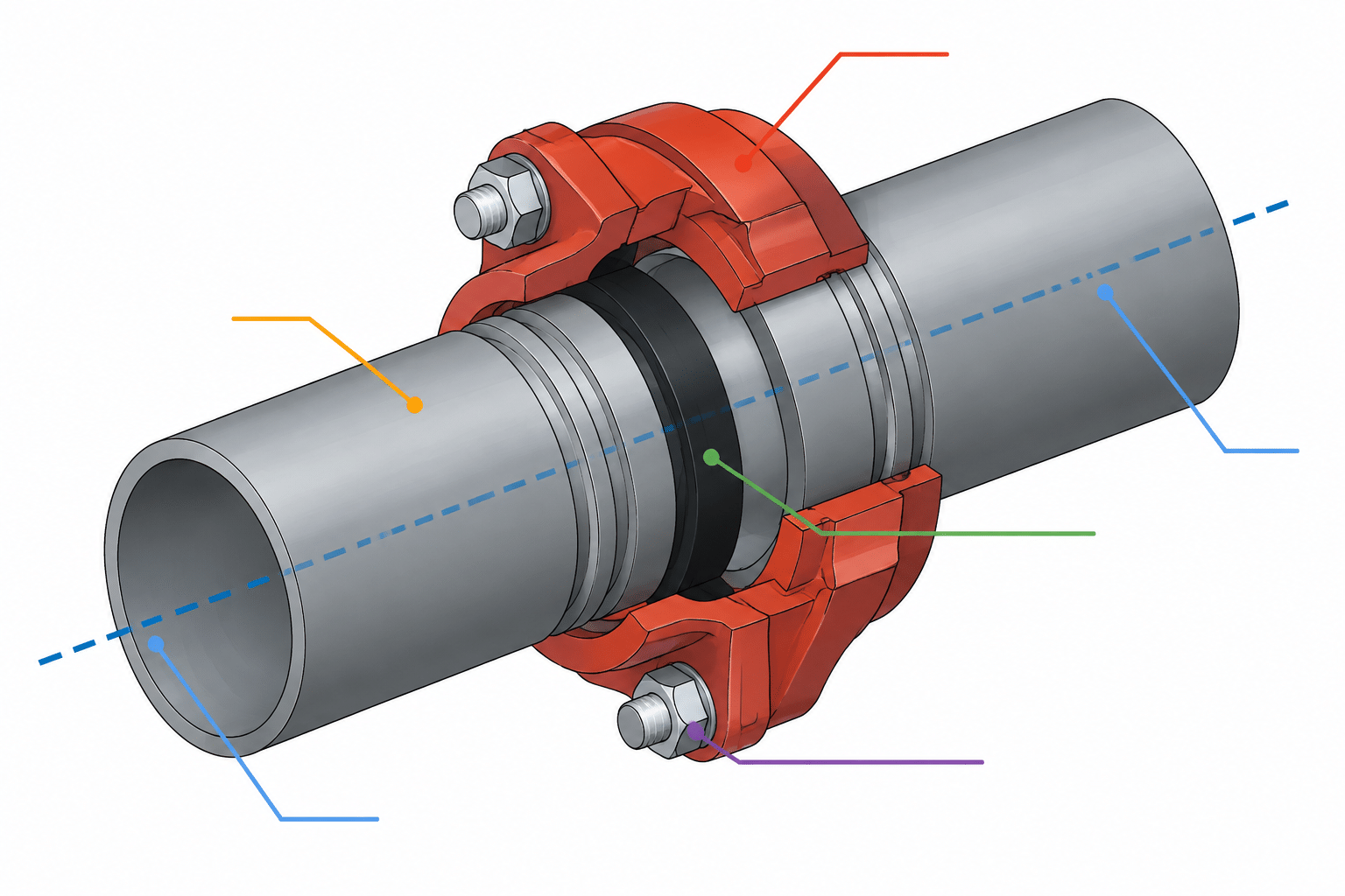
  • Grooved Pipe Connections in CAD: Couplings, End Gaps, and Cut-Length Control

    Grooved Pipe Connections in CAD: Couplings, End Gaps, and Cut-Length Control

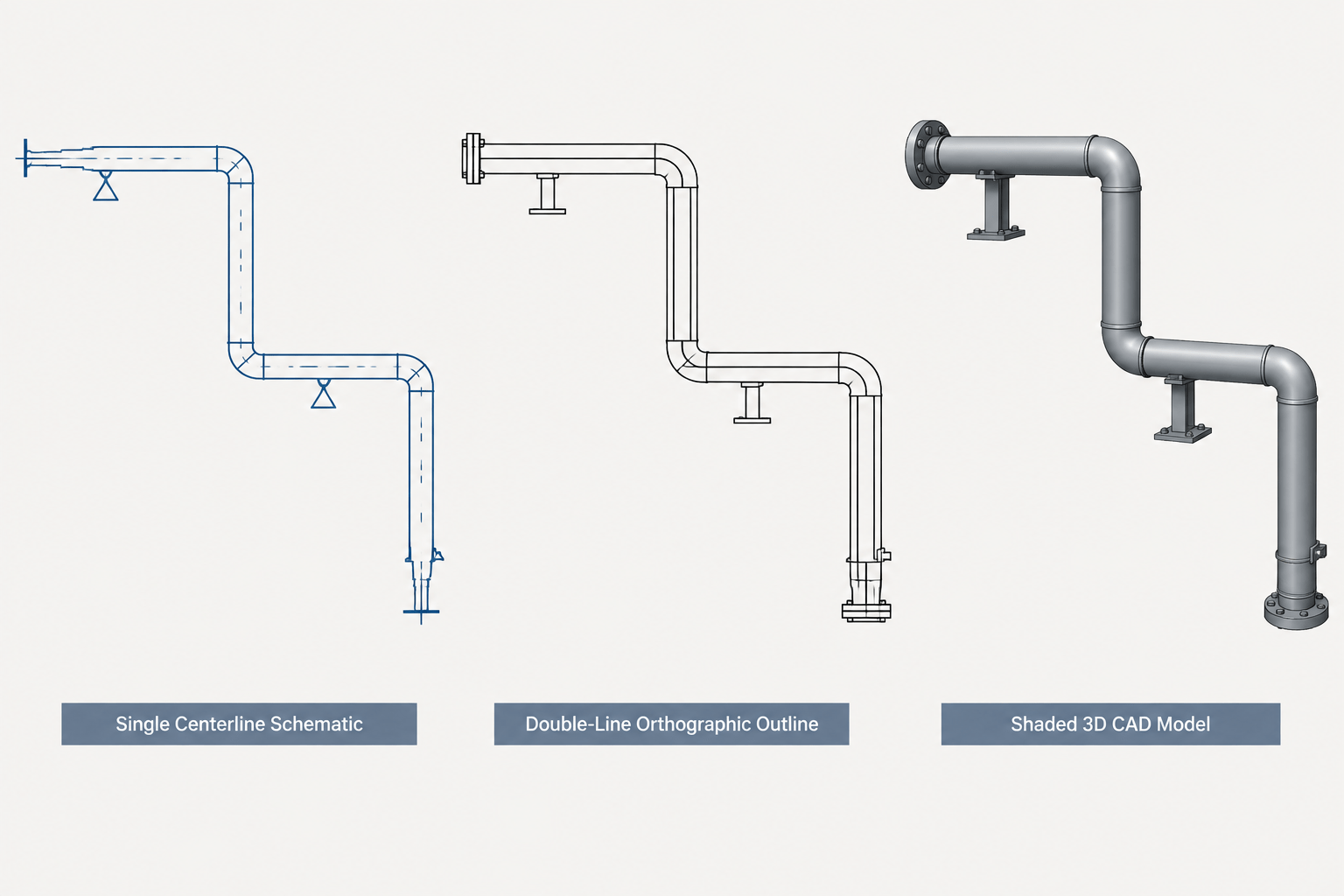
  • Single-Line, Double-Line, and 3D Piping Drawings: Choosing the Right CAD Representation

    Single-Line, Double-Line, and 3D Piping Drawings: Choosing the Right CAD Representation

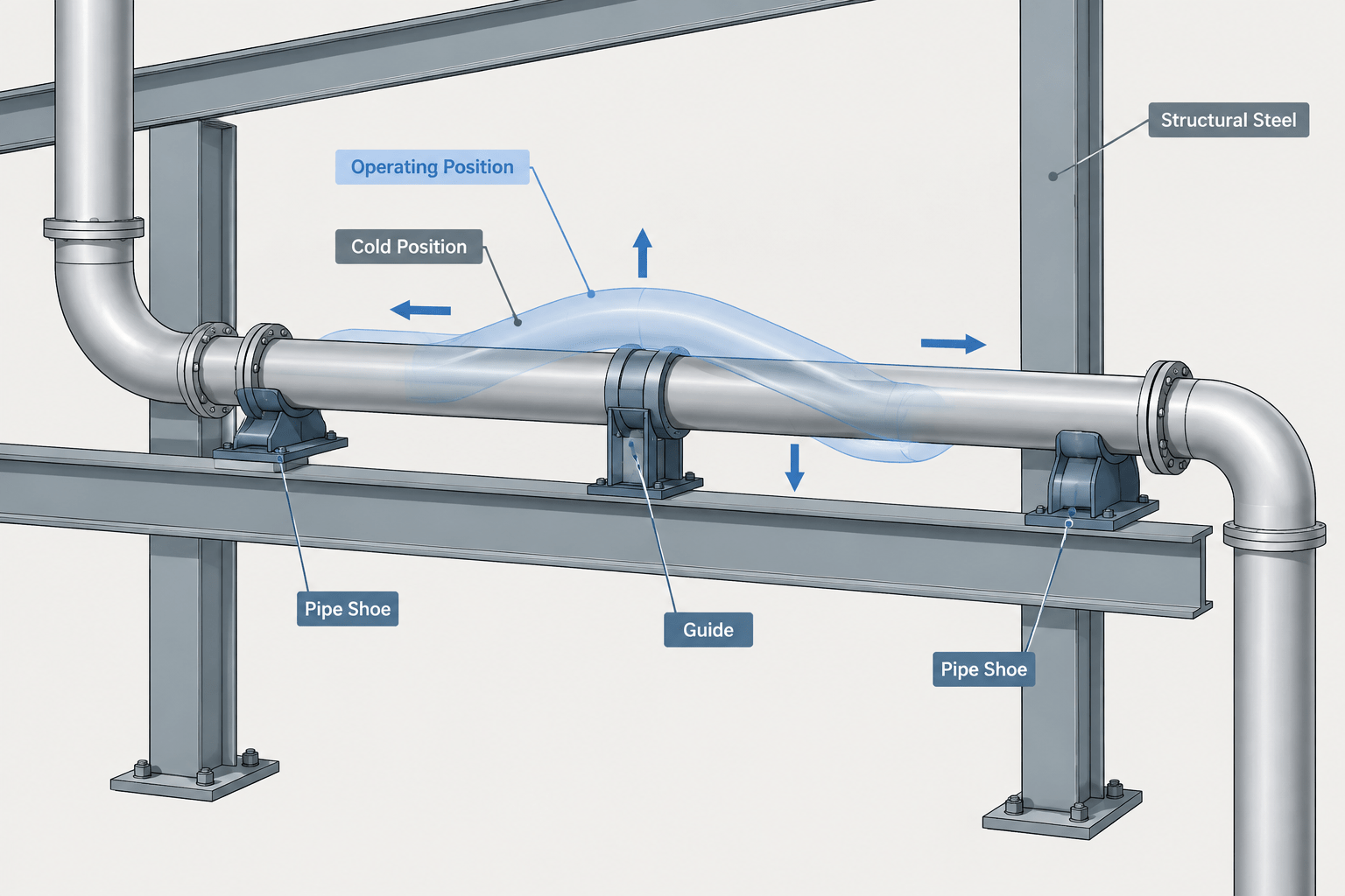
  • Cold Position vs. Hot Position in Piping CAD: How to Document Thermal Movement Clearly

    Cold Position vs. Hot Position in Piping CAD: How to Document Thermal Movement Clearly

  • Nominal Geometry vs. Fabrication Tolerance in Piping CAD: A Practical Detailing Guide

    Nominal Geometry vs. Fabrication Tolerance in Piping CAD: A Practical Detailing Guide