Tag: CAD workflow

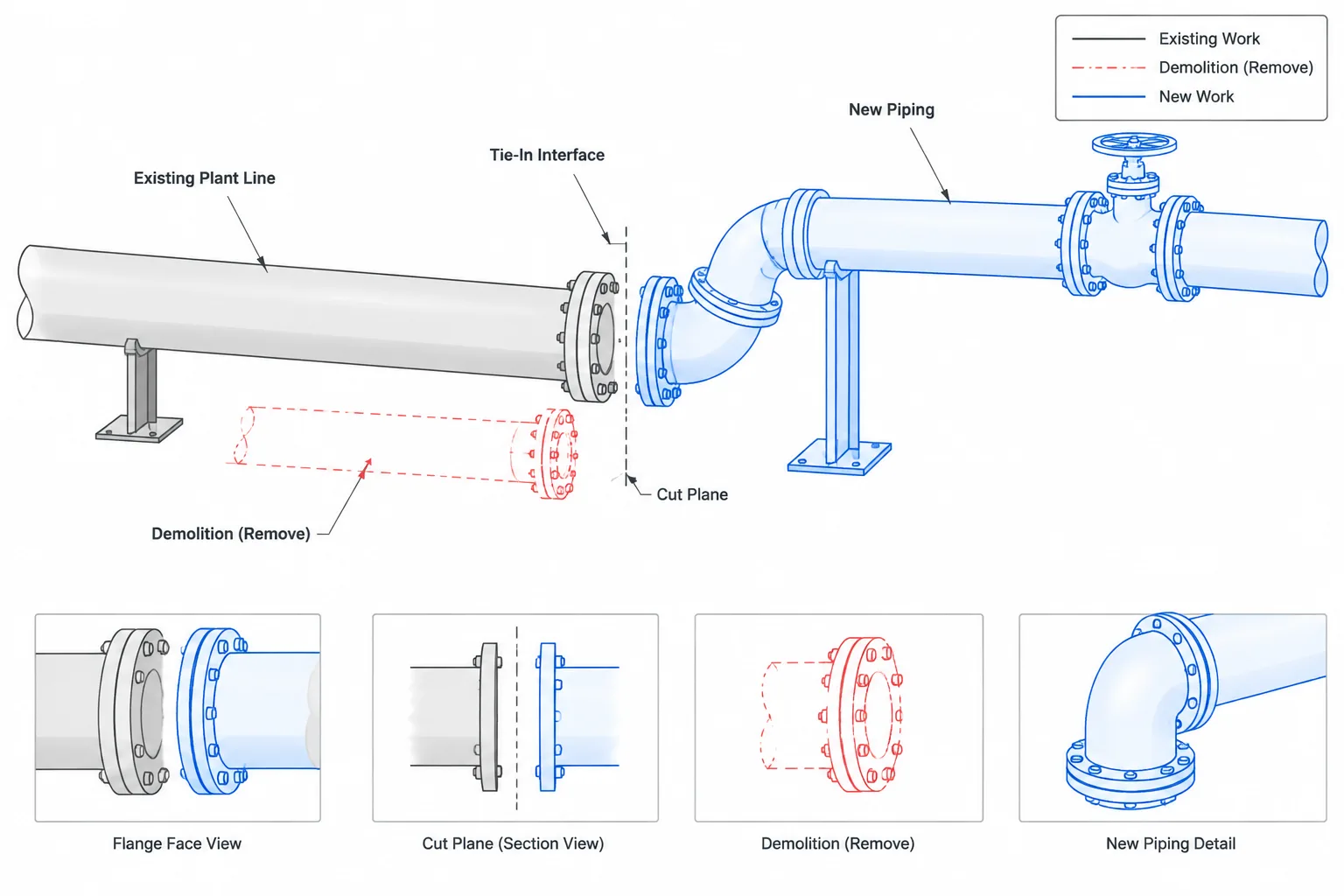
  • Piping Tie-In Points in CAD: Existing-System Interfaces, Field Verification, and Drawing Control

    Piping Tie-In Points in CAD: Existing-System Interfaces, Field Verification, and Drawing Control

  • Pipe Roughness in Flow Calculations: Absolute Roughness, Relative Roughness, and CAD Data

    Pipe Roughness in Flow Calculations: Absolute Roughness, Relative Roughness, and CAD Data

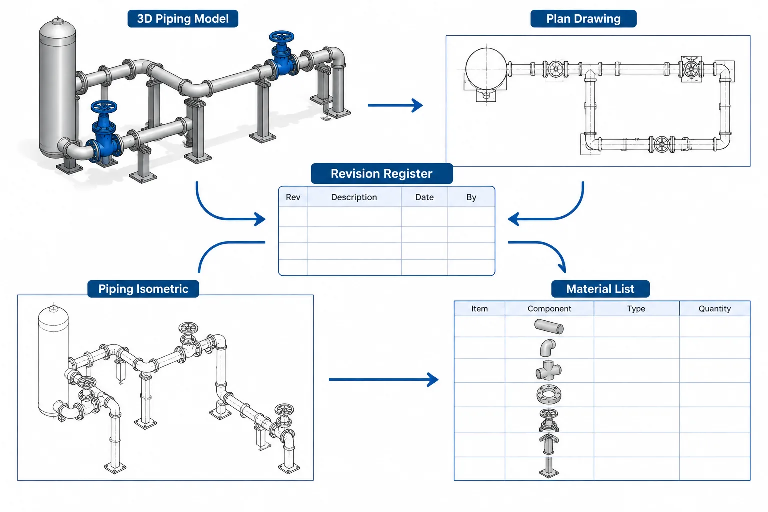
  • Piping CAD Revision Control: How to Track Model, Drawing, and Data Changes

    Piping CAD Revision Control: How to Track Model, Drawing, and Data Changes

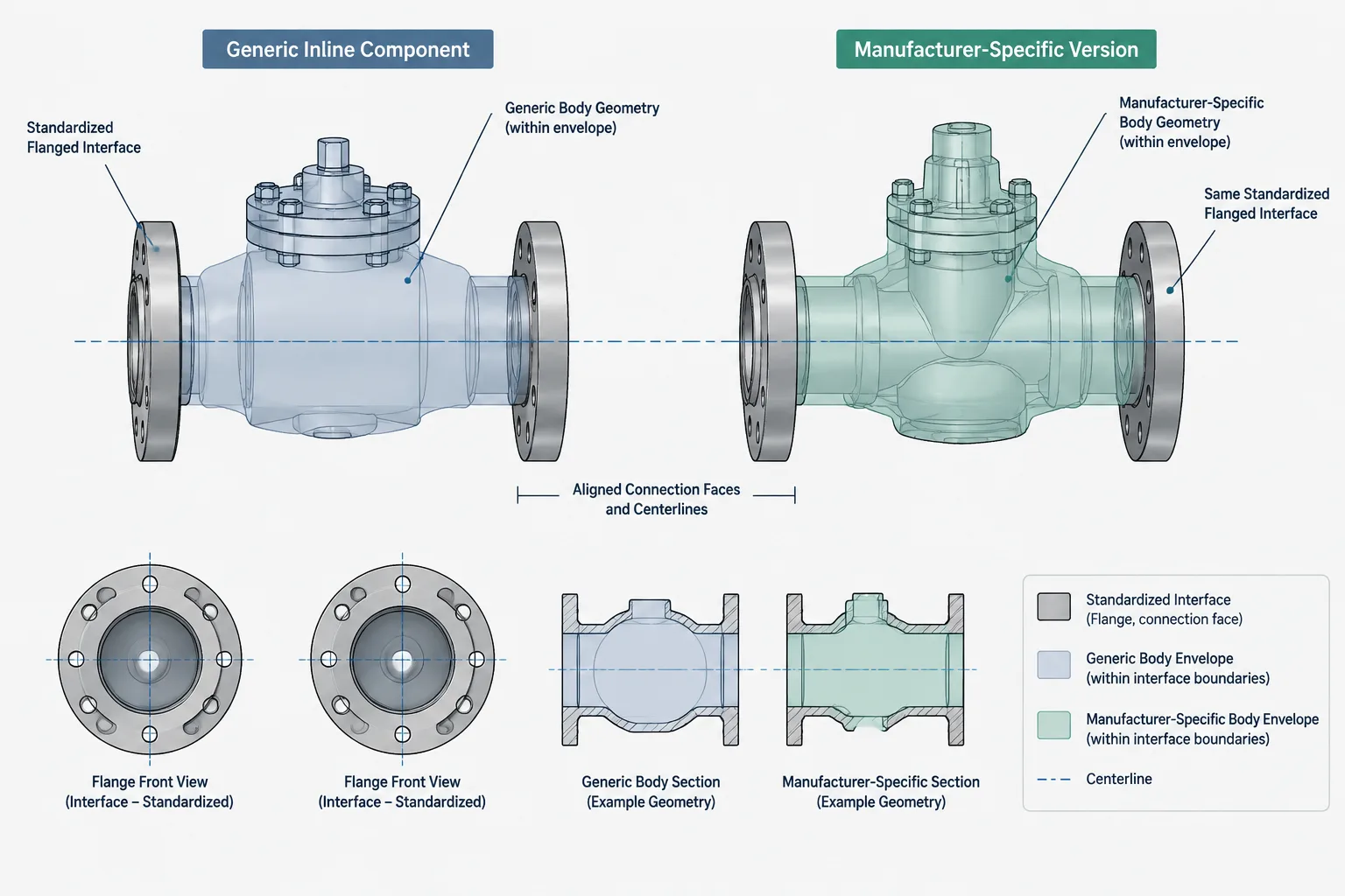
  • Standard Dimensions vs. Manufacturer Dimensions in Piping CAD: What Can Be Treated as Generic?

    Standard Dimensions vs. Manufacturer Dimensions in Piping CAD: What Can Be Treated as Generic?

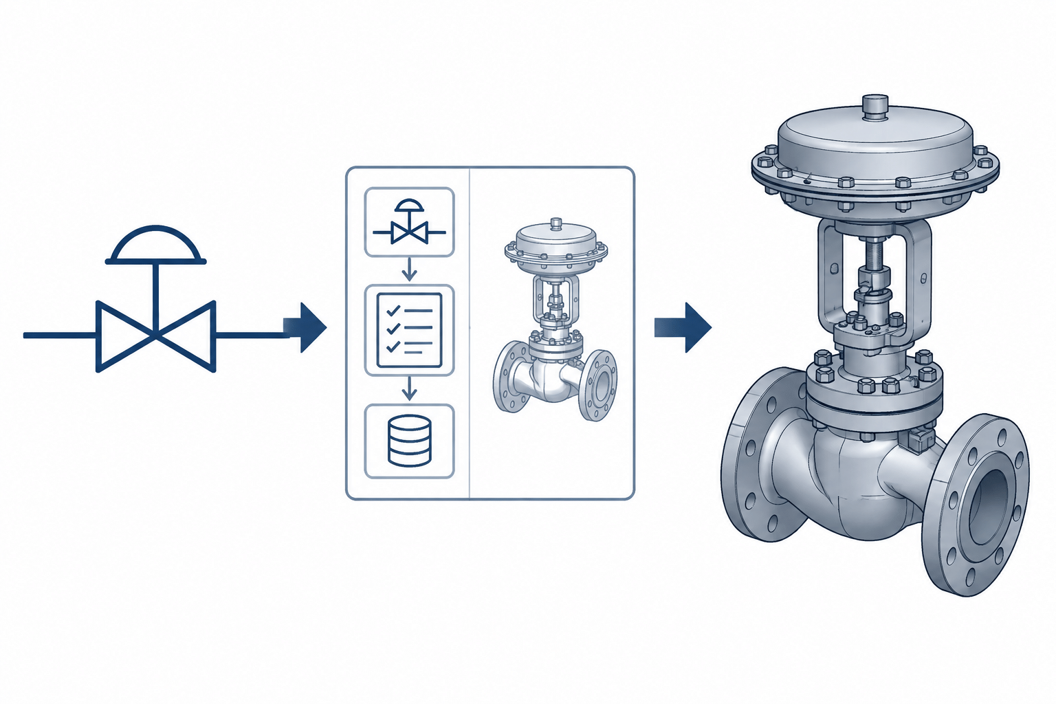
  • P&ID Symbols vs. 3D Piping Components: How to Translate Process Intent into CAD

    P&ID Symbols vs. 3D Piping Components: How to Translate Process Intent into CAD

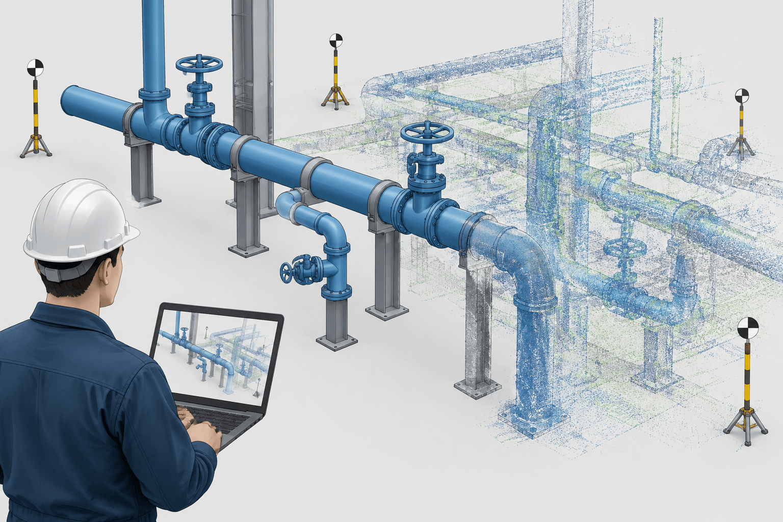
  • As-Built Piping Drawings in CAD: A Field Verification and Update Workflow

    As-Built Piping Drawings in CAD: A Field Verification and Update Workflow

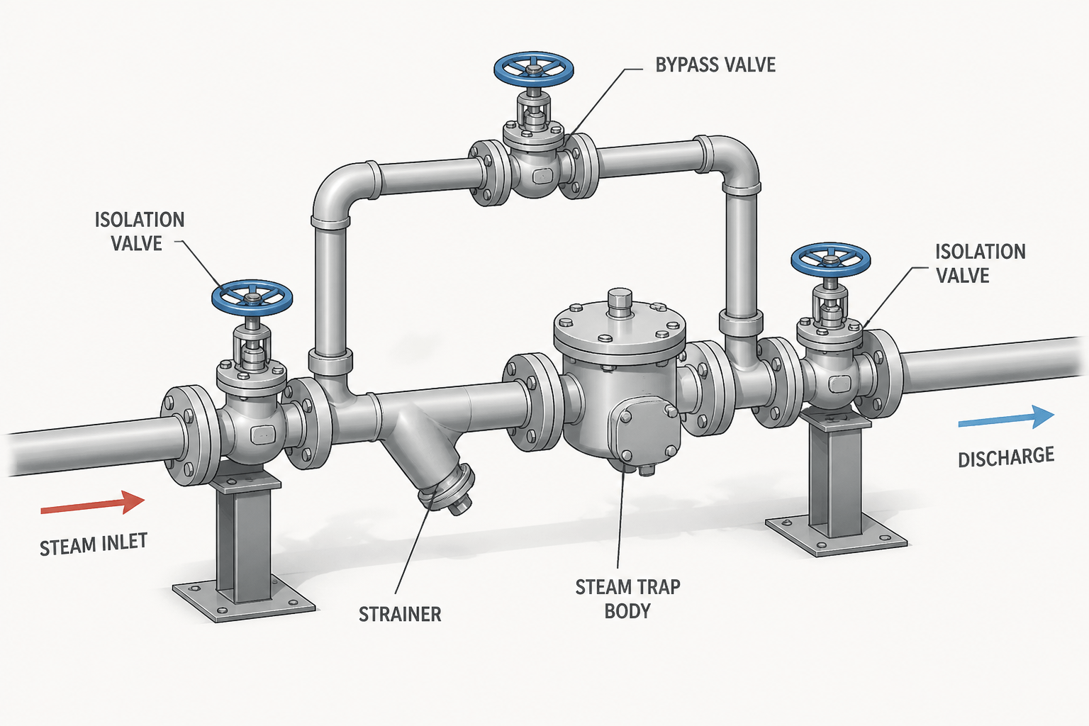
  • Steam Trap Piping in CAD: How to Show Stations, Bypass Lines, and Drainage Details

    Steam Trap Piping in CAD: How to Show Stations, Bypass Lines, and Drainage Details

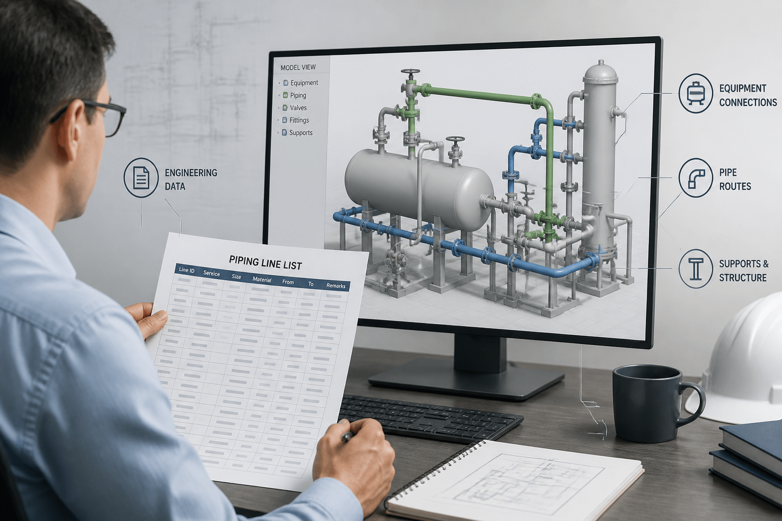
  • How to Read a Piping Line List Before CAD Modeling

    How to Read a Piping Line List Before CAD Modeling

  • Long-Radius vs Short-Radius Pipe Elbows: How to Read and Detail Them in CAD

    Long-Radius vs Short-Radius Pipe Elbows: How to Read and Detail Them in CAD