Tag: piping isometrics

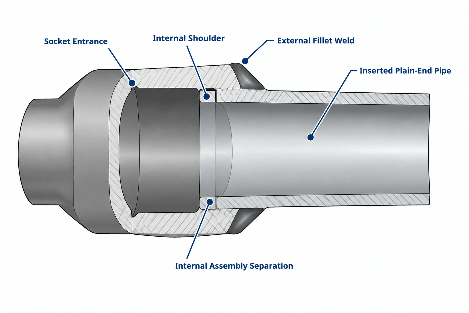
  • Socket-Weld Piping in CAD: Insertion Depth, Assembly Gap, and Cut-Length Control

    Socket-Weld Piping in CAD: Insertion Depth, Assembly Gap, and Cut-Length Control

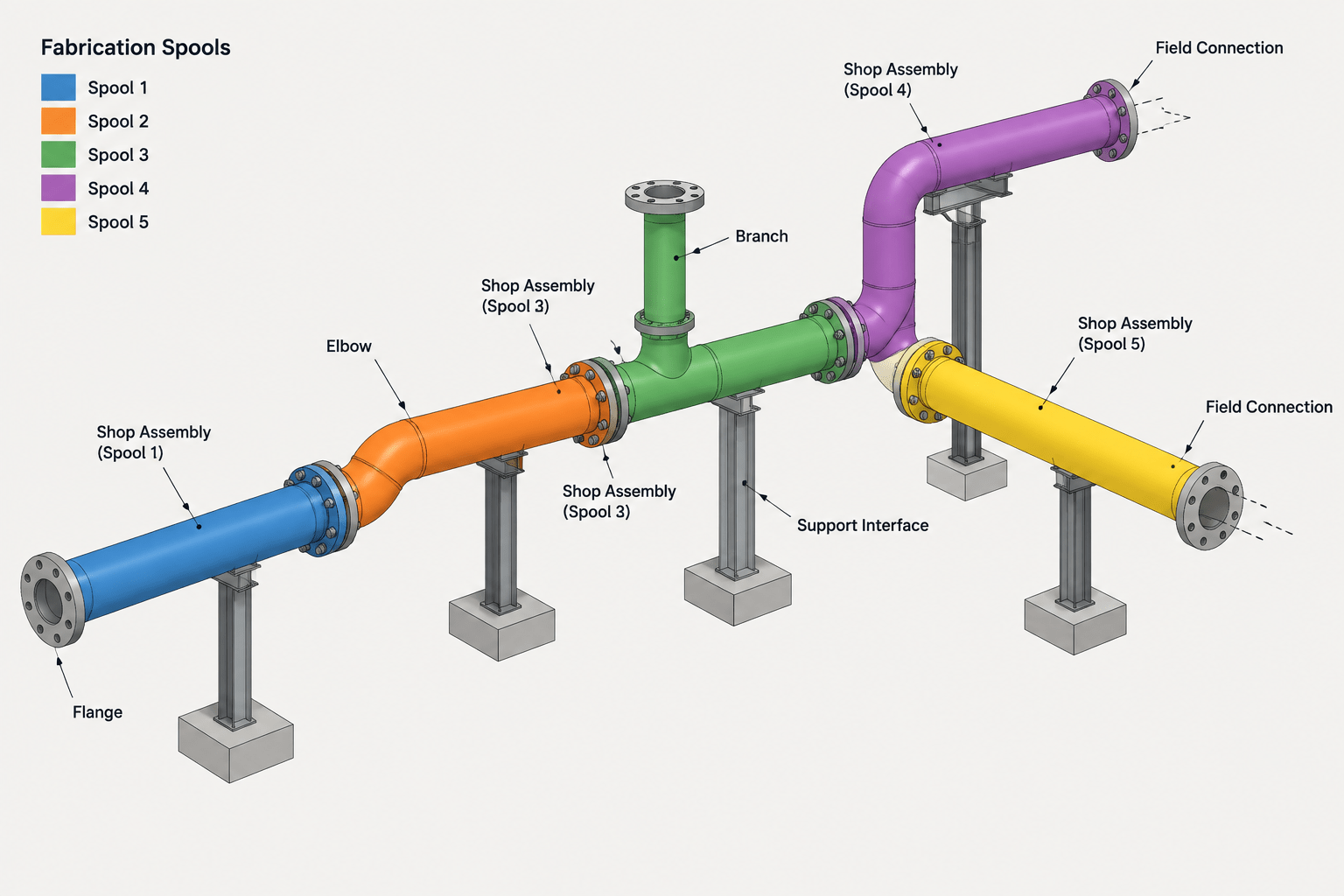
  • Piping Spool Breaks in CAD: Planning Fabrication, Transport, and Field Assembly

    Piping Spool Breaks in CAD: Planning Fabrication, Transport, and Field Assembly

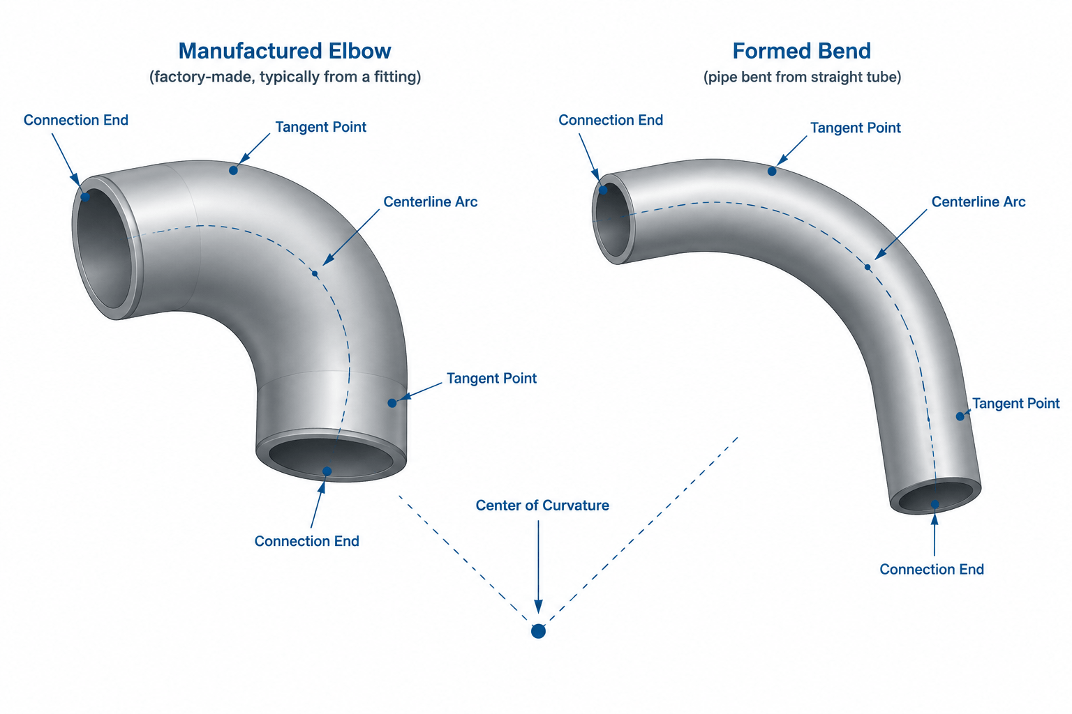
  • Pipe Bends vs. Elbows in CAD: Geometry, Tangent Points, and Documentation

    Pipe Bends vs. Elbows in CAD: Geometry, Tangent Points, and Documentation

  • Nominal Geometry vs. Fabrication Tolerance in Piping CAD: A Practical Detailing Guide

    Nominal Geometry vs. Fabrication Tolerance in Piping CAD: A Practical Detailing Guide

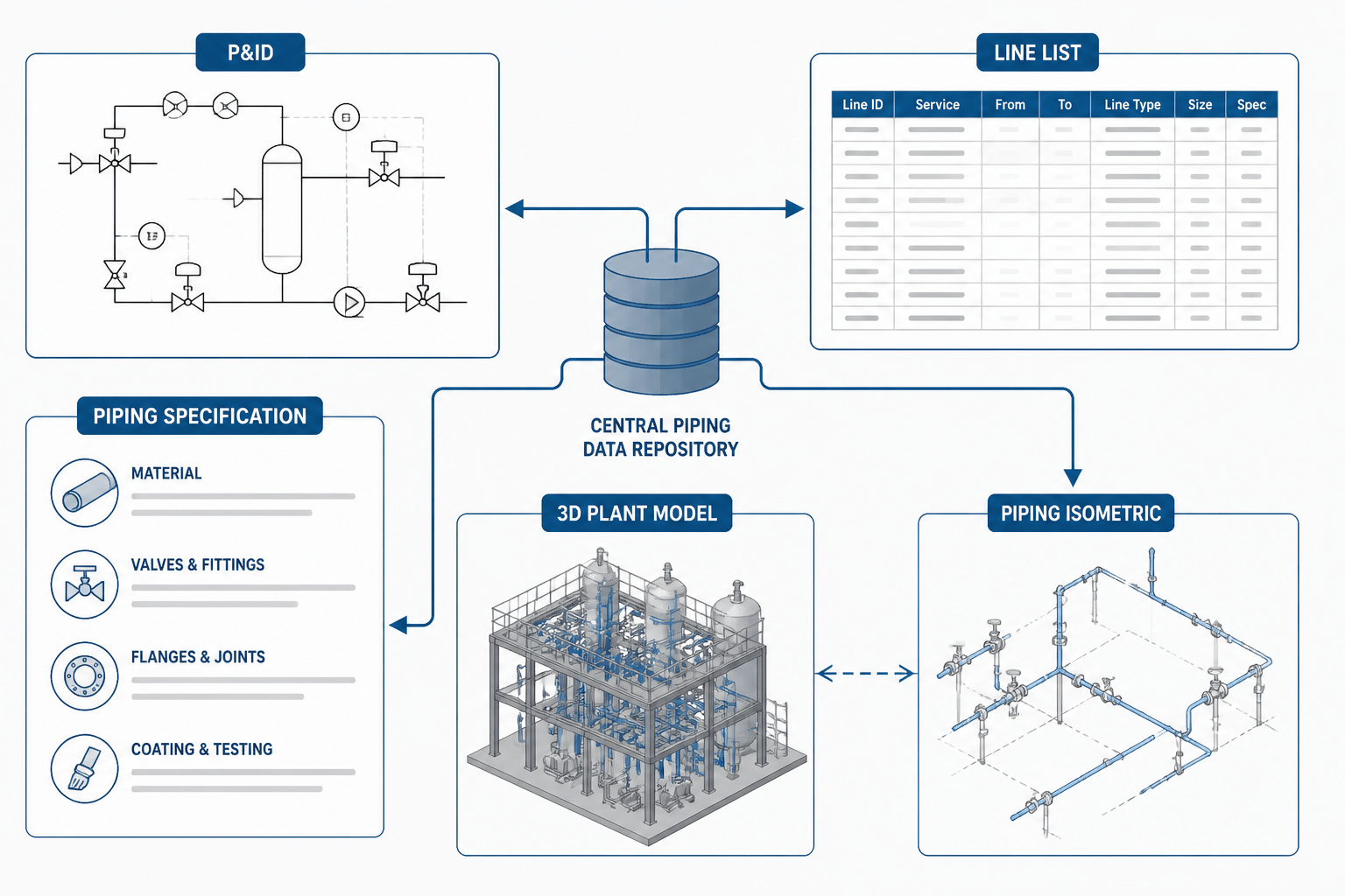
  • Piping Document Handoffs: How P&IDs, Line Lists, Isometrics, and CAD Models Work Together

    Piping Document Handoffs: How P&IDs, Line Lists, Isometrics, and CAD Models Work Together

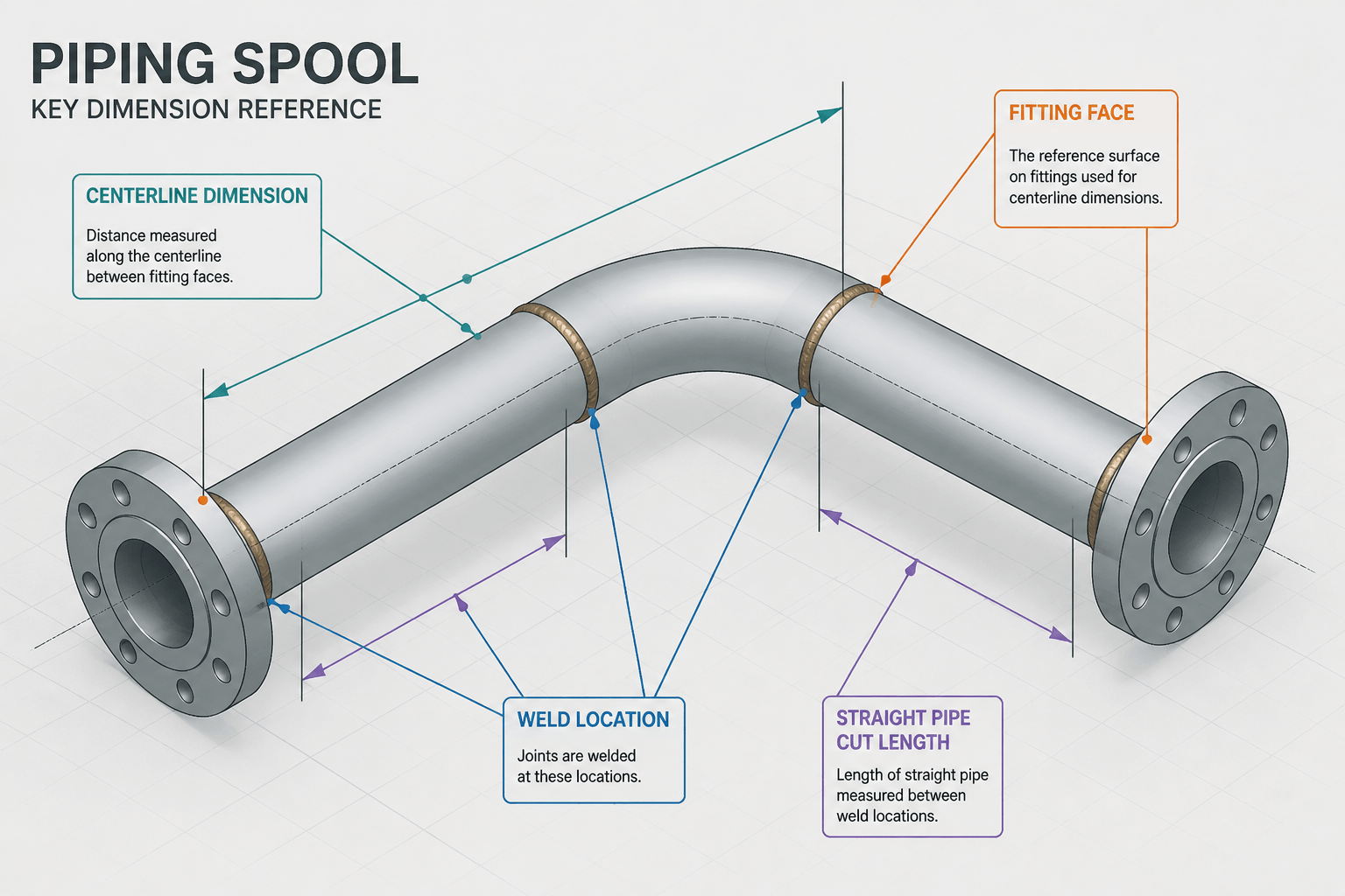
  • Piping Takeoff Dimensions vs. Cut Lengths: Why CAD Measurements Differ

    Piping Takeoff Dimensions vs. Cut Lengths: Why CAD Measurements Differ

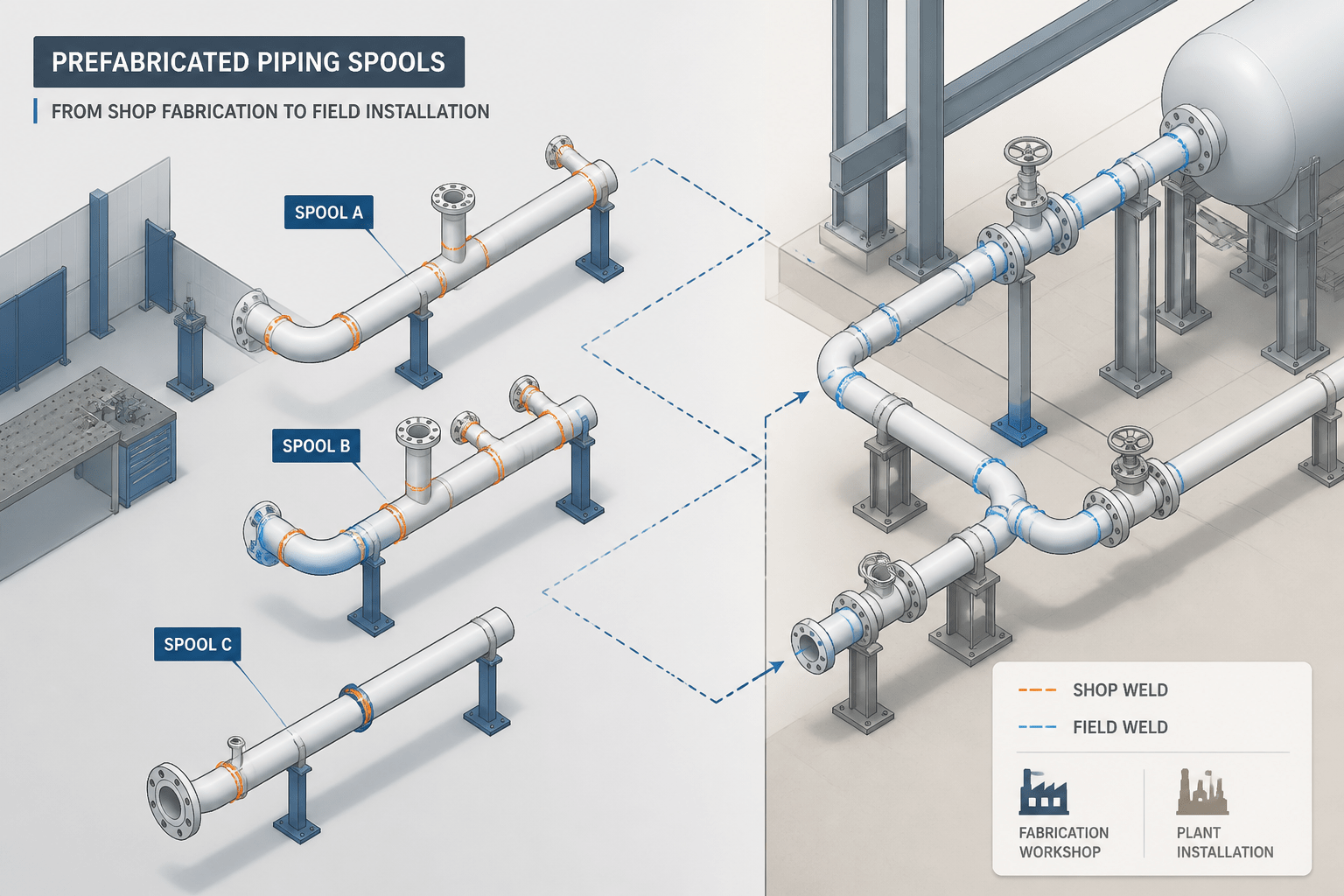
  • Piping Isometric Shop Welds vs. Field Welds: A Practical CAD Detailing Guide

    Piping Isometric Shop Welds vs. Field Welds: A Practical CAD Detailing Guide

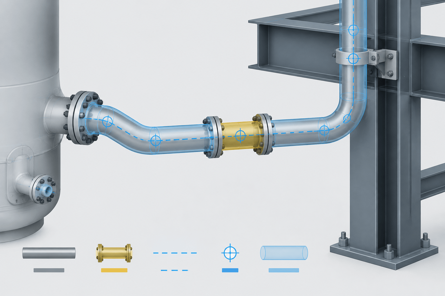
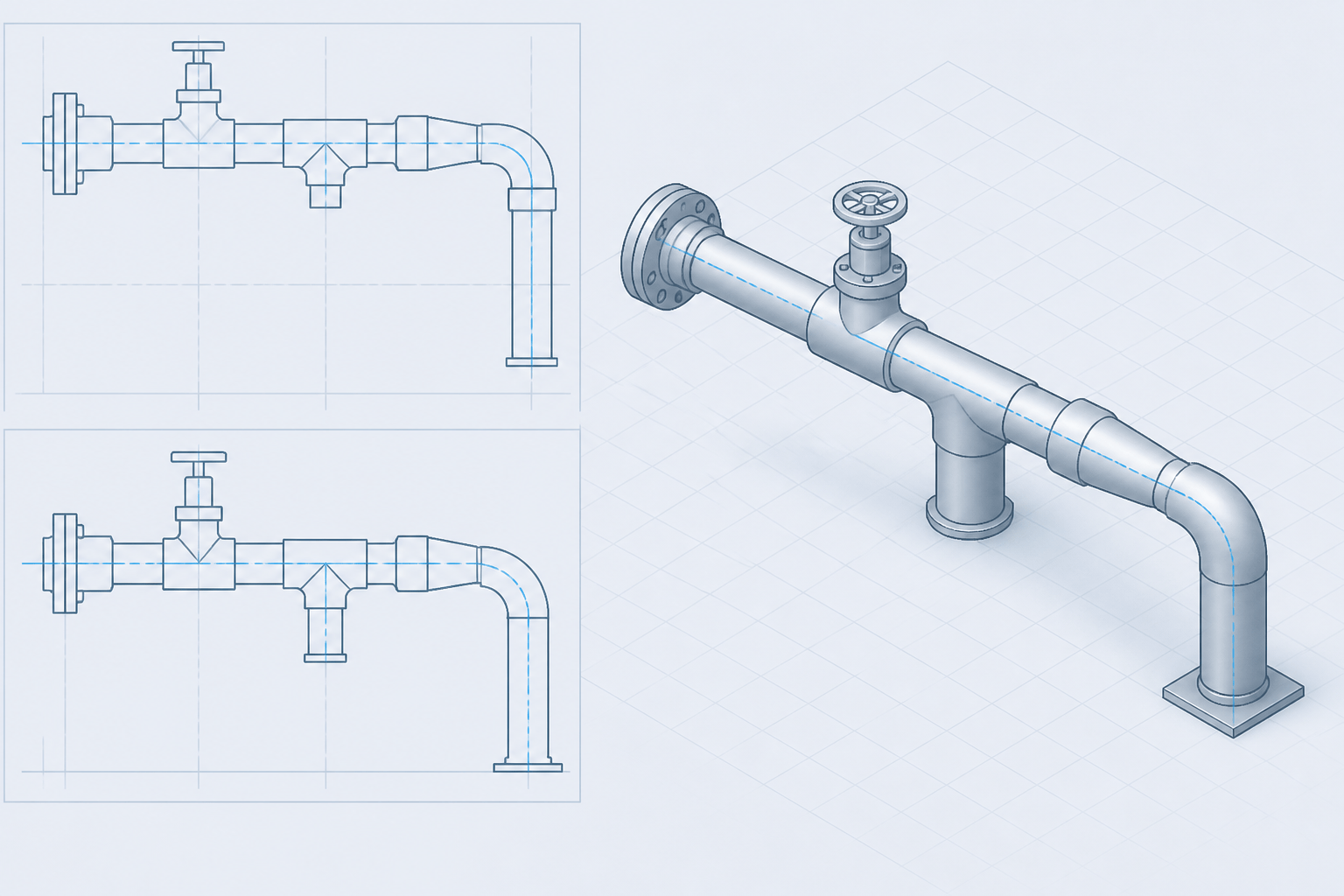
  • Piping CAD Centerline Modeling: A Practical Guide to Routing, Fittings, and Dimensions

    Piping CAD Centerline Modeling: A Practical Guide to Routing, Fittings, and Dimensions

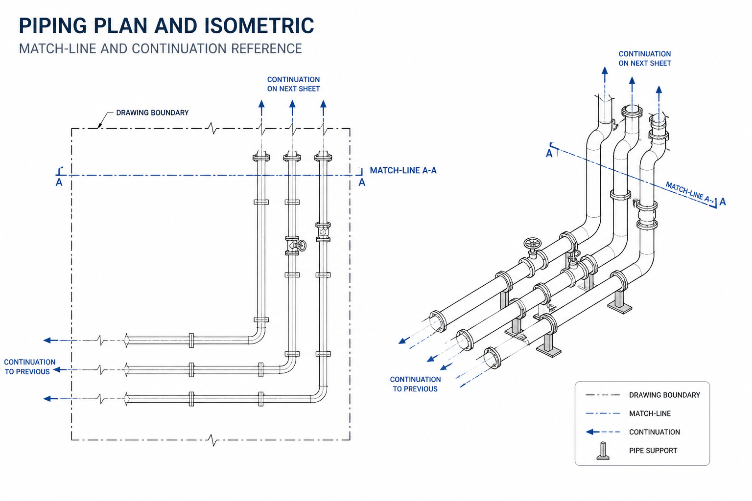
  • Piping Drawing Match Lines and Continuation Symbols: A Practical CAD Guide

    Piping Drawing Match Lines and Continuation Symbols: A Practical CAD Guide