Tag: piping isometrics

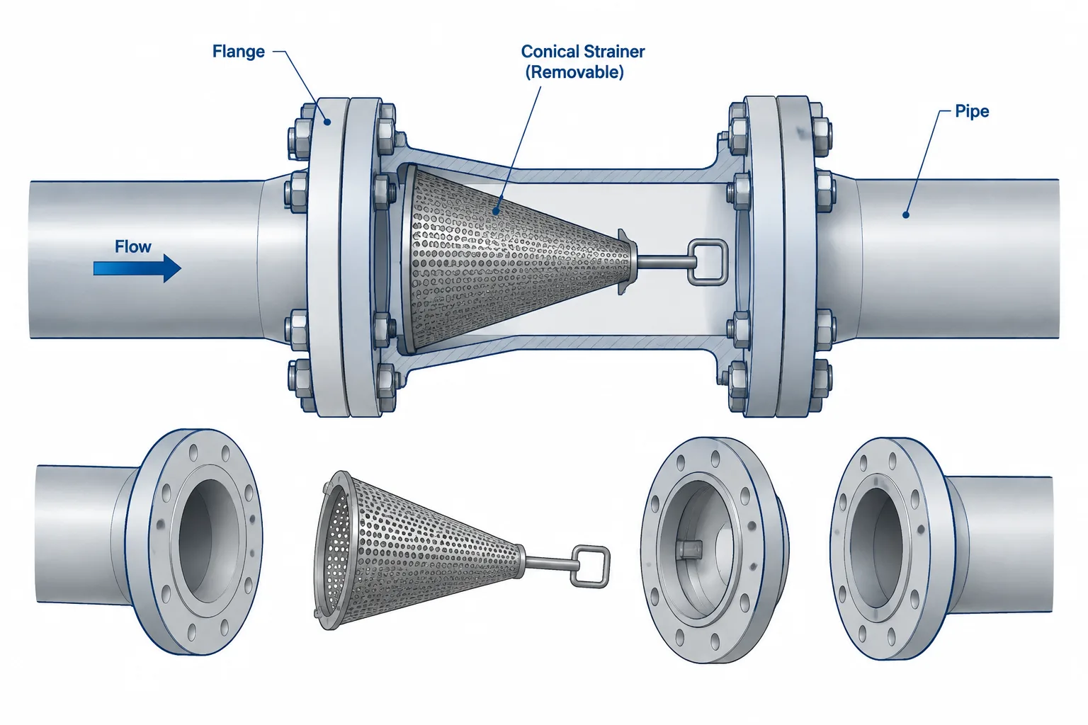
  • Temporary Strainers in Piping CAD: Placement, Orientation, and Removal Planning

    Temporary Strainers in Piping CAD: Placement, Orientation, and Removal Planning

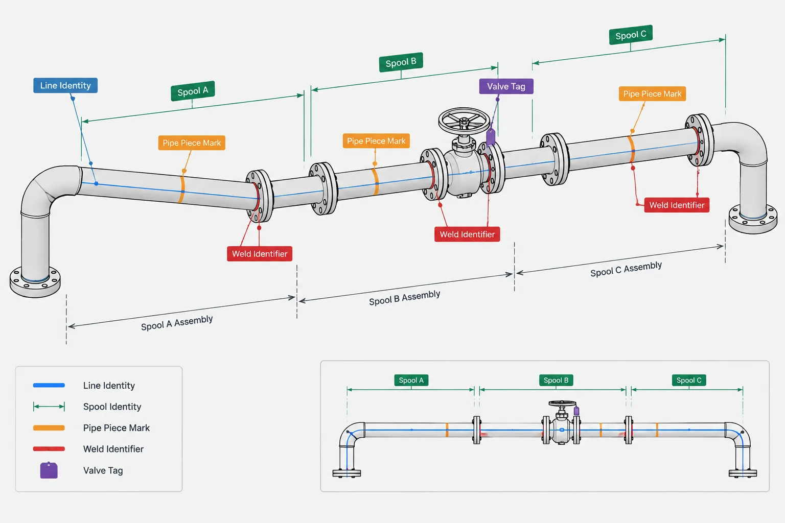
  • Pipe Spool Numbers, Piece Marks, and Line Numbers: What Each Identifier Controls

    Pipe Spool Numbers, Piece Marks, and Line Numbers: What Each Identifier Controls

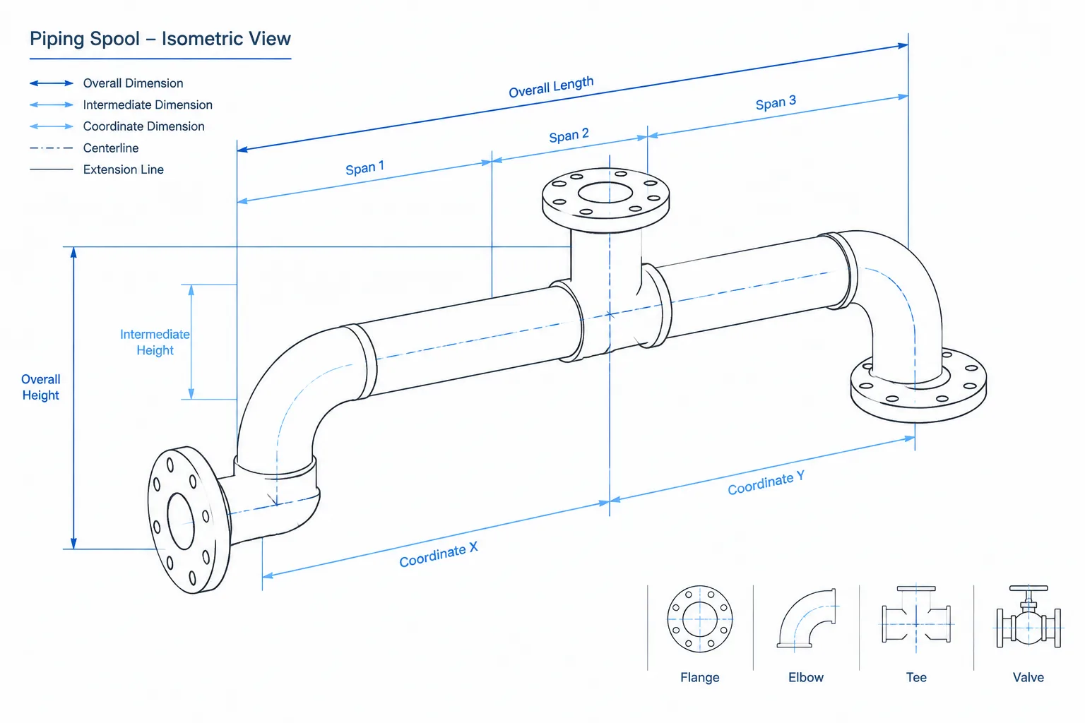
  • Piping Isometric Dimensioning: What to Control and What to Leave Derived

    Piping Isometric Dimensioning: What to Control and What to Leave Derived

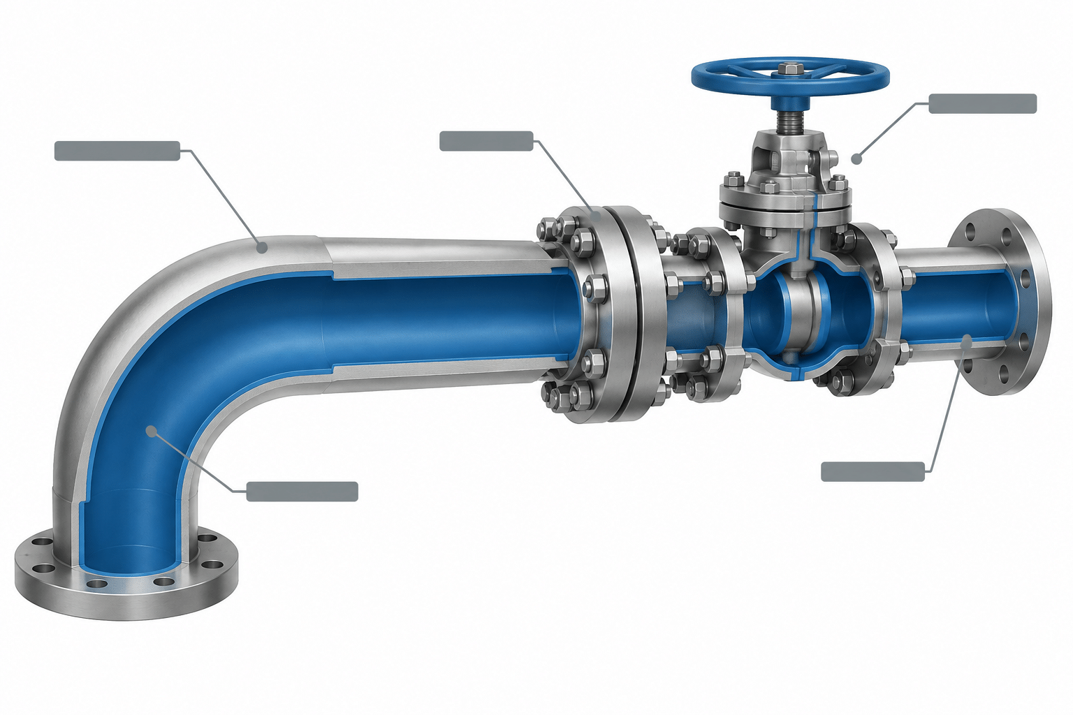
  • Lined Piping in CAD: How to Model, Specify, and Detail the Internal Barrier

    Lined Piping in CAD: How to Model, Specify, and Detail the Internal Barrier

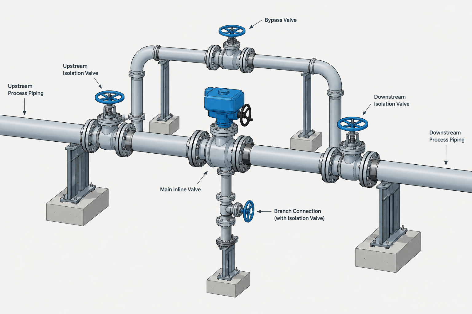
  • Valve Bypass Piping in CAD: Isolation, Operation, and Maintenance Layout

    Valve Bypass Piping in CAD: Isolation, Operation, and Maintenance Layout

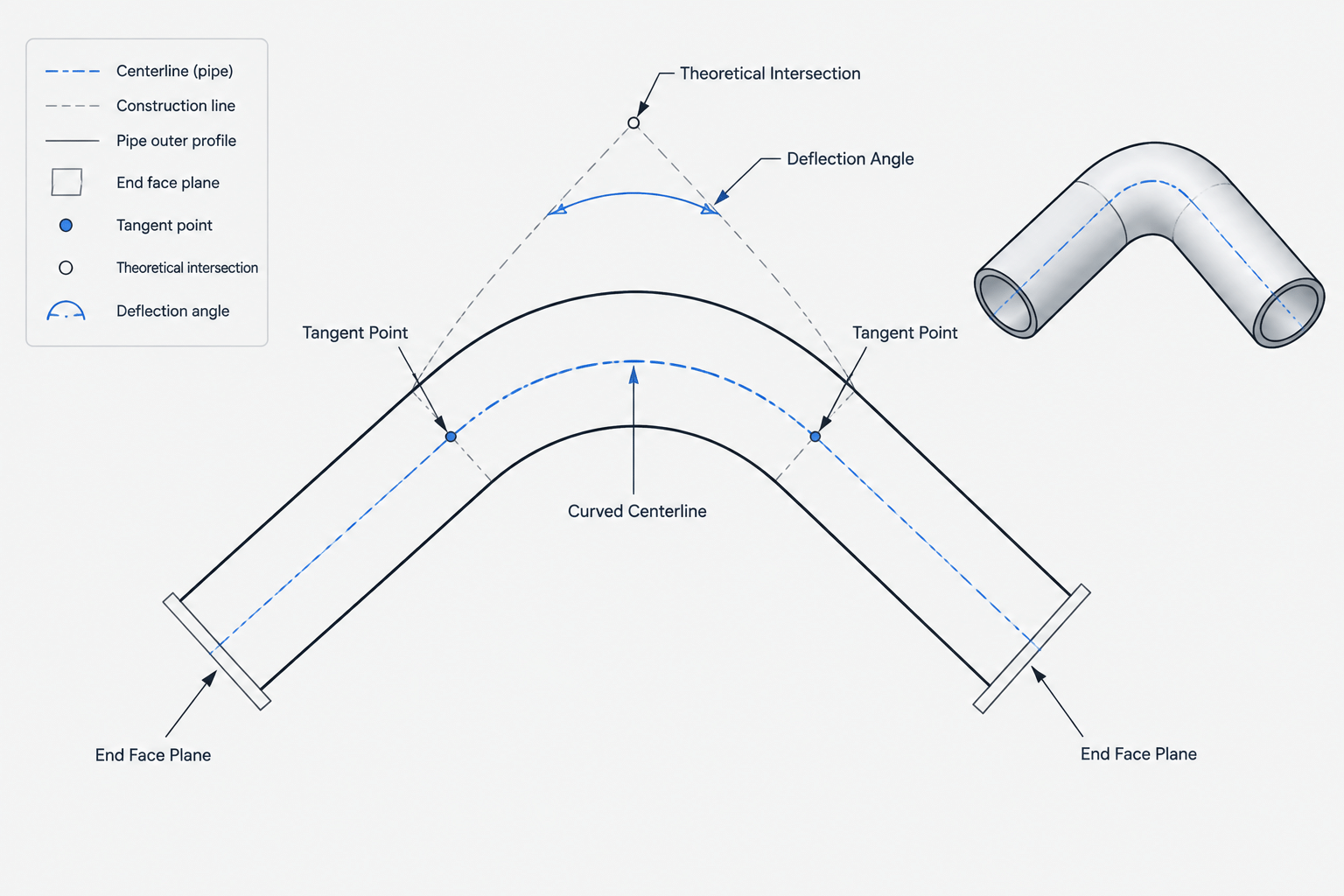
  • Trimmed Pipe Elbows in CAD: Geometry, Takeout, and Fabrication Documentation

    Trimmed Pipe Elbows in CAD: Geometry, Takeout, and Fabrication Documentation

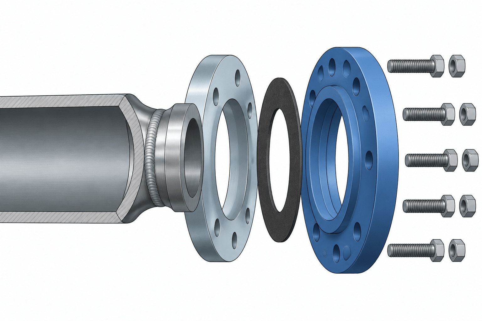
  • Lap Joint Flanges and Stub Ends in Piping CAD: Assembly, Rotation, and Dimension Control

    Lap Joint Flanges and Stub Ends in Piping CAD: Assembly, Rotation, and Dimension Control

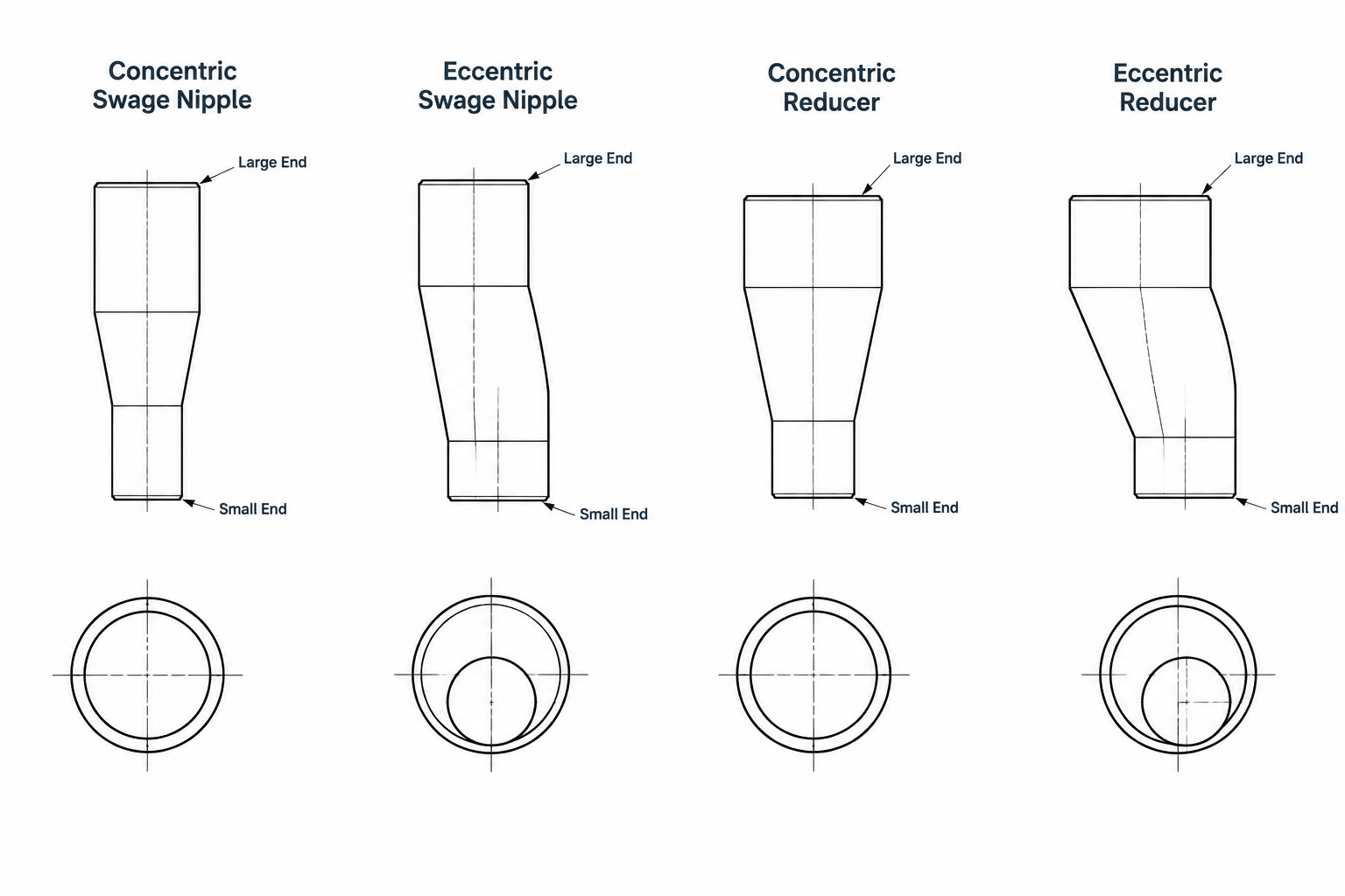
  • Swage Nipples vs. Pipe Reducers: Selection, Connections, and CAD Detailing

    Swage Nipples vs. Pipe Reducers: Selection, Connections, and CAD Detailing

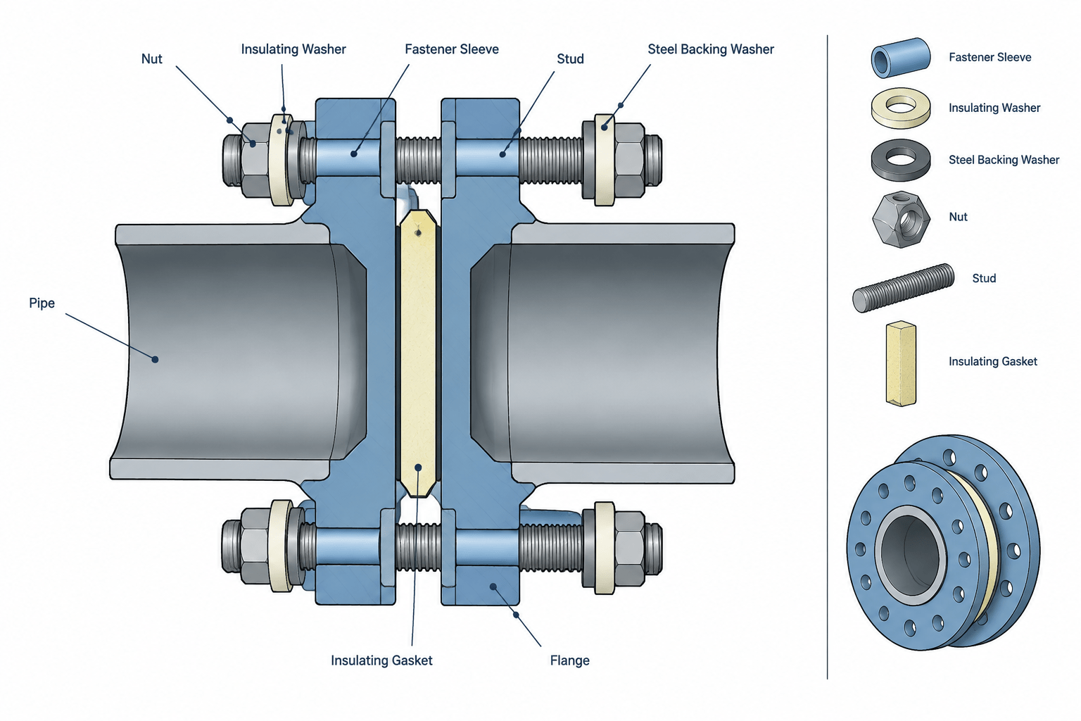
  • Flange Isolation Kits in Piping CAD: Gaskets, Sleeves, Washers, and Joint Stack-Up

    Flange Isolation Kits in Piping CAD: Gaskets, Sleeves, Washers, and Joint Stack-Up