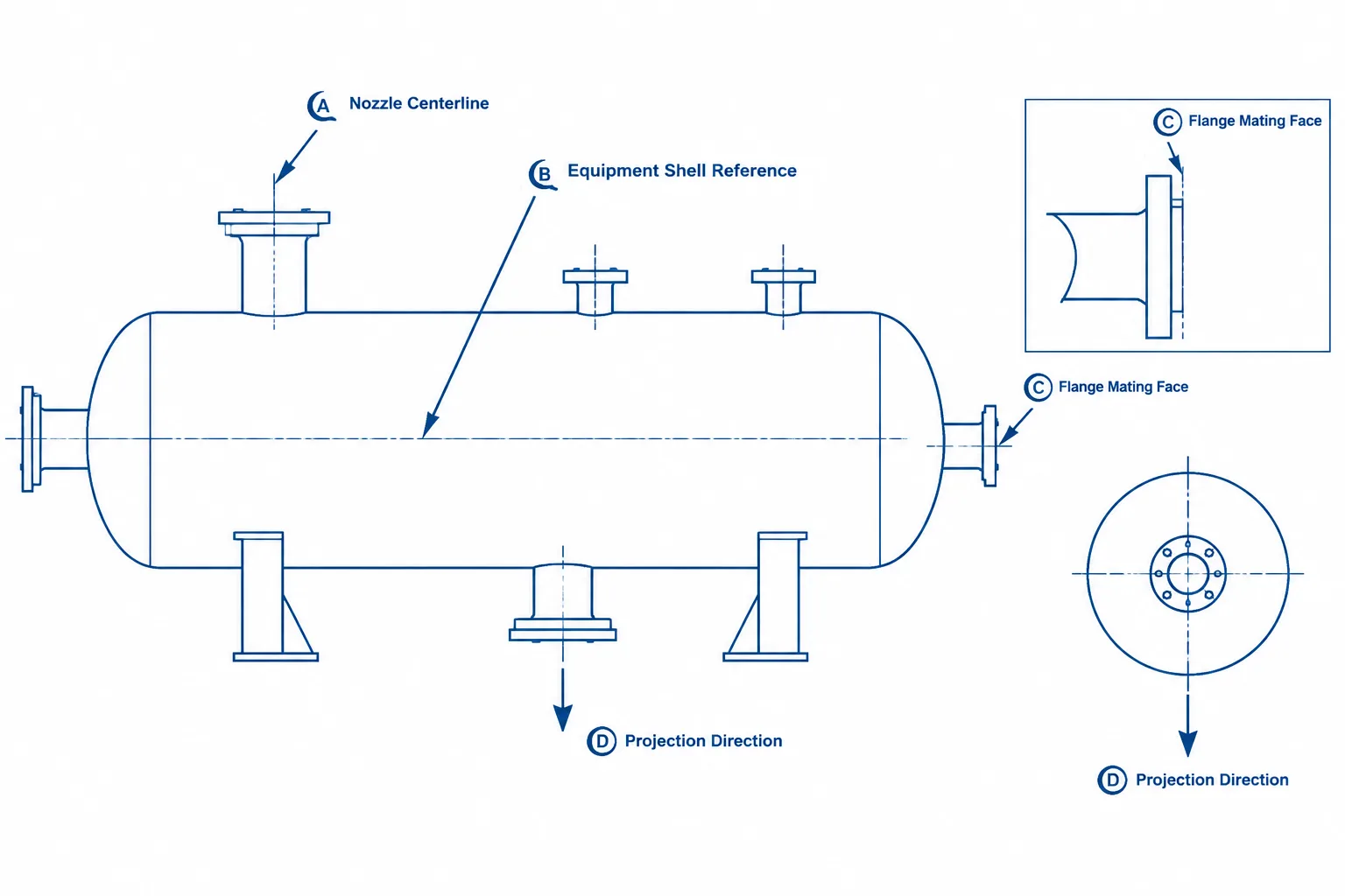
Equipment nozzle projection in piping CAD is best understood as a controlled interface definition rather than a simple extension from an equipment outline. The model must identify where the measurement begins, the direction in which it is applied, and the connection plane where piping geometry takes over.
This guide explains how to interpret projection references, distinguish flange faces from other nozzle endpoints, manage preliminary vendor information, and review the resulting equipment-to-piping connection. The objective is not merely to make the nozzle look correct, but to make its modeled location traceable and suitable for coordinated design review.
Equipment nozzle projection is a small dimension with a large effect on piping layout. It establishes how far a nozzle connection extends from the equipment and, therefore, where the connected piping begins. If the projection is interpreted from the wrong reference point, a model may contain the correct nozzle orientation and connection size but still place the flange face or weld end in the wrong location.
The difficulty is that “nozzle projection” is not always measured from the same type of point. Depending on the equipment, connection, vendor drawing, and project convention, it may originate at a vessel shell, tank plate, equipment centerline, tangent line, base reference, or another defined surface. The terminating point may be a flange face, pipe end, coupling face, or another connection datum. CAD users should therefore treat projection as a defined relationship between two references, not as a standalone length.
What Equipment Nozzle Projection Controls
A nozzle projection locates the connection point relative to the equipment. It can affect:
- The position of the first piping flange, weld, or threaded connection.
- The required length of the connecting spool.
- Valve and fitting clearances near the equipment.
- Access to flange bolts, instruments, drains, and insulation.
- Loads created by piping alignment or forced fit-up.
- The location of pipe supports near the equipment interface.
- Removal space for equipment heads, covers, bundles, or internal components.
Projection should not be confused with nozzle orientation. Orientation identifies where the nozzle is located around or on the equipment, while projection establishes how far the connection extends outward. Both are required to locate a nozzle connection in three-dimensional space.
Identify the Projection Reference Point
Before entering a projection into CAD, identify the exact point from which it is measured. A dimension labeled only as “projection” may be ambiguous when separated from its drawing view or notes.
Equipment centerline
Some equipment drawings locate a nozzle face or end directly from a vessel, tank, or machine centerline. In this case, the stated dimension includes the radial distance through the equipment body as well as the portion extending beyond its exterior. It should not be treated as a shell-to-face dimension.
Shell or plate surface
A projection may begin at the nominal outside surface of a shell, head, roof, wall, or other plate. The drafter should determine whether the reference represents the modeled outer surface, a theoretical surface, or a fabrication reference shown by the equipment supplier.
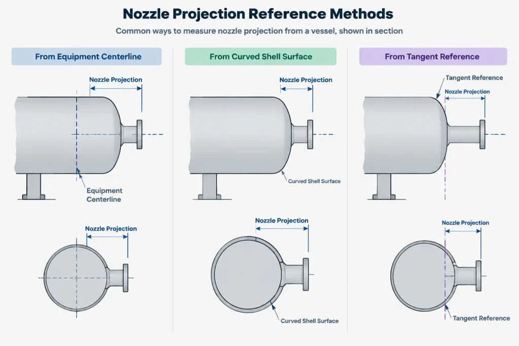
For curved equipment, a shell-surface reference requires particular care. The reference should be taken where the nozzle centerline intersects the defined shell surface, not from a convenient nearby point in a plan or elevation view.
Tangent line or other equipment datum
Vessels and similar equipment may use tangent lines, seam lines, base lines, or other construction datums to locate nozzles. A dimension from a tangent line may control the nozzle’s axial location, while a separate projection dimension controls its outward extension. These dimensions perform different functions and should remain separate in the model data.
Insulation or cladding surface
Insulation is normally an envelope rather than the fundamental nozzle-location datum, unless the supplier or project documentation explicitly defines it otherwise. Using the visible insulation surface as the projection origin can shift a nozzle connection relative to the actual equipment geometry.
Identify the Nozzle Connection Point
The outer end of the projection must also be defined. The appropriate CAD connection point depends on the nozzle end type.
| Nozzle end | Typical connection datum to verify | Common modeling concern |
|---|---|---|
| Flanged | Flange mating face | Confusing the flange face with the hub end or flange center |
| Butt-weld | Prepared pipe or neck end | Extending the model to an implied weld location not shown by the supplier |
| Socket-weld | Fitting face or defined port datum | Using the internal socket bottom as the external piping connection point |
| Threaded | External fitting face or defined threaded endpoint | Assuming visible thread length represents final makeup position |
| Coupled or proprietary connection | Supplier-defined mating plane | Substituting a generic component without confirming the interface |
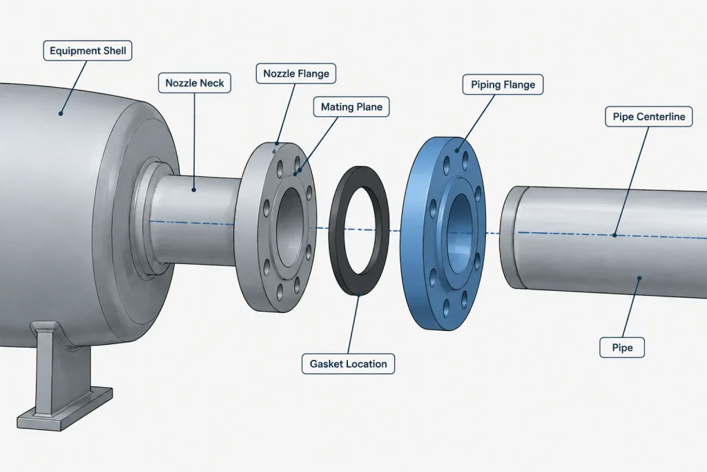
For a flanged nozzle, the mating face is usually the most useful piping interface because the connecting gasket and piping flange assemble at that plane. However, the source drawing must confirm that its dimension actually terminates at the face. A dimension to the flange centerline, back of flange, or end of nozzle neck cannot be entered as a face location without accounting for the omitted geometry.
Nozzle Projection and Equipment Geometry
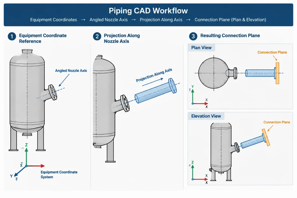
The nozzle’s direction determines how its projection is applied. A radial nozzle on a cylindrical shell projects along a line that passes through the equipment axis. A top nozzle may project vertically, while a nozzle on a formed head may be normal to the local surface or oriented along another defined axis. An angled nozzle requires its true centerline direction before its endpoint can be located correctly.
Do not apply projection only in a drawing’s horizontal or vertical direction unless the nozzle axis is actually aligned that way. For an inclined connection, the projection belongs along the nozzle centerline. Its plan, elevation, and axial coordinate changes are derived from that direction.
A simplified equipment model can make this relationship difficult to see. For example, a generic cylinder may omit the actual head contour, reinforcement, or transition on which the nozzle is mounted. Simplification is acceptable for many layout purposes, but the nozzle connection point should still be driven by verified interface data rather than by snapping to approximate graphics.
A Practical CAD Modeling Workflow
1. Establish the equipment coordinate system
Place the equipment using the project coordinate system and identify its controlling centerlines, base elevation, tangent lines, and orientation references. Confirm whether the equipment model represents nominal geometry, vendor geometry, or a preliminary layout envelope.
2. Create the nozzle axis
Locate the nozzle around the equipment using the specified orientation and axial or vertical position. Define a centerline vector pointing outward from the equipment. This axis should remain distinguishable from the projection length.
3. Define the inner projection reference
Create or identify the shell surface, equipment centerline, tangent reference, or other origin stated by the source document. Avoid silently replacing a difficult reference with an easier modeling point.
4. Place the connection plane
Measure along the nozzle axis to the verified flange face, weld end, or other connection plane. Use that plane as the piping interface. If the project uses intelligent piping components, the nozzle port should coincide with this location and point in the correct connection direction.
5. Separate piping geometry from equipment geometry
The equipment nozzle belongs to the equipment interface, while the mating flange, gasket, and downstream spool belong to the piping assembly. Keeping ownership clear helps prevent duplicate flanges, omitted gaskets, and overlapping geometry.
6. Record the source and status
Indicate whether the nozzle location is preliminary, based on a vendor proposal, or taken from controlled equipment documentation. A visually complete model should not imply that an unverified interface is final.
Preliminary Data and Vendor Updates
Equipment nozzles often enter a model before final supplier information is available. The layout may begin with process requirements, a preliminary equipment outline, and assumed nozzle locations. These assumptions should be managed as changeable data rather than embedded in disconnected CAD solids.
Useful nozzle attributes include the equipment tag, nozzle identifier, connection size, end type, orientation, elevation or axial position, projection reference, connection-point definition, data source, and revision status. The required attributes vary by project, but the objective is consistent: make the geometry traceable to its controlling information.
When revised equipment data arrives, compare more than the projection value. Check whether the reference datum, flange type, facing, connection direction, equipment origin, or nozzle identifier has changed. An unchanged number can still produce a different endpoint if its reference definition has changed.
Common Projection Errors
- Measuring from insulation: The nozzle is shifted because the insulation envelope was mistaken for the equipment surface.
- Using the back of a flange: The piping interface is misplaced because the dimension should terminate at the mating face.
- Ignoring curvature: Projection is measured from a bounding box or plan-view edge instead of the defined shell intersection.
- Applying an angled length horizontally: The displayed dimension is entered on a coordinate axis rather than along the nozzle centerline.
- Double-counting the flange: The equipment model already includes a nozzle flange, and the piping model adds another flange at the same interface.
- Treating preliminary geometry as certified: Downstream piping is finalized around an assumed nozzle position without a documented hold or review.
- Updating graphics but not data: A nozzle solid moves, but its port, tag, dimensions, or connected spool remains at the previous location.
How to Check the Interface
A nozzle review should verify the complete interface rather than projection alone. Confirm that the nozzle tag matches the equipment documentation, the axis points in the intended direction, and the connection plane matches the stated endpoint. Check the flange face or weld end coordinates against the controlling references.
Then review the connected piping. Look for coincident centerlines, compatible end types, adequate joint representation, and realistic access around flanges and nearby components. Confirm that insulation, platforms, structural steel, and removable equipment parts do not conflict with the connection.
On drawings, dimension the feature from stable equipment or project datums. Avoid creating redundant dimensions that independently control the same nozzle endpoint. If projection is shown, its origin and endpoint should be visually or textually unambiguous.
Projection Is an Interface Definition
The most reliable way to manage equipment nozzle projection in piping CAD is to define it as an interface between equipment and piping. The model needs a known origin, a known nozzle axis, and a known mating point. A length without those definitions is incomplete.
By separating orientation, axial location, projection, and end-connection geometry, designers can update vendor information without rebuilding the surrounding layout blindly. This approach also makes reviews more effective: instead of asking whether the nozzle “looks right,” the project team can verify exactly which references locate the piping connection.
Managing Nozzle Projection Through Model Handoffs
Nozzle information may pass through process, equipment, piping, structural, and supplier workflows. Each handoff creates an opportunity for the projection definition to lose context. A coordinate or length copied into another document is not sufficient unless its origin, direction, endpoint, and revision status remain identifiable.
A practical handoff should distinguish between the equipment geometry being represented and the piping connection being controlled. The nozzle body may be simplified, but the interface plane should remain consistent with the approved source. Conversely, a highly detailed flange model does not validate the connection if its face was positioned from an assumed datum.
Information to retain with the interface
- The equipment and nozzle identifiers used by the controlling documentation.
- The datum or surface from which projection is measured.
- The nozzle centerline direction and orientation basis.
- The defined piping connection point, such as a mating face or prepared end.
- The source, approval state, and revision status of the nozzle information.
- Any modeling assumption that remains subject to supplier confirmation.
Use Coordinates as a Check, Not a Substitute for Definition
Endpoint coordinates are useful for comparing an equipment model, piping model, and drawing. They do not explain how the endpoint was established. If equipment geometry moves or its project origin changes, a coordinate-only check may conceal an incorrect projection relationship.
The strongest review combines both methods: verify the nozzle from its controlling equipment references, then confirm the resulting connection-point coordinates. This provides a geometric check while preserving the design intent behind the location.
Model Detail and Interface Accuracy Are Different
Nozzle necks, reinforcement, flange hubs, and facing details can improve visualization and interference review, but they should not obscure the primary connection datum. CAD teams should be able to identify the piping interface without relying on the visual edge of a complex component.
Where intelligent ports are used, the port origin and connection direction should agree with the visible geometry. Where basic solids or reference models are used, a clearly controlled plane, point, or centerline can provide the same interface discipline. In either case, the model representation should make ownership clear and support revision without forcing users to infer the mating location.
Final Review Question
Before releasing connected piping, ask whether another designer can determine exactly what locates the nozzle face or end without relying on appearance alone. If the origin, axis, endpoint, or source remains uncertain, the projection should be treated as unresolved interface data rather than a completed connection.
Equipment Nozzle Projection FAQ
Is nozzle projection the same as nozzle orientation?
No. Orientation establishes the direction or circumferential position of the nozzle. Projection establishes where the connection endpoint lies along the nozzle axis. Both are needed to locate the piping interface.
For a flanged nozzle, which point should connect to the piping model?
The applicable connection plane is generally the flange mating face, but the controlling equipment documentation must confirm the dimension endpoint. A dimension to another part of the flange cannot be assumed to locate the mating face.
Can projection be measured from the equipment centerline?
Yes, when the source documentation defines the centerline as the origin. Such a dimension includes the distance through the equipment geometry and must not be interpreted automatically as an extension from the shell surface.
Should the insulation surface be used as the nozzle projection origin?
Only when the controlling documentation explicitly defines it that way. Insulation is commonly modeled as an outer envelope and should not silently replace the equipment or fabrication datum.
How should an angled nozzle projection be entered in CAD?
Apply the projection along the verified nozzle centerline. Do not enter the full projection as a horizontal, vertical, or axial coordinate change unless the nozzle axis is aligned with that direction.
What should be checked when revised vendor information is received?
Review the reference datum, equipment origin, nozzle axis, endpoint definition, end connection, identifier, and revision status in addition to the projection entry itself. The same displayed length may locate a different point if its definition has changed.
Can simplified equipment geometry still support accurate piping layout?
Yes, provided the nozzle interface is controlled by verified references rather than approximate model edges. Visual simplification and interface accuracy are separate considerations.
How can duplicate flanges be prevented?
Define which flange belongs to the equipment model and where the piping assembly begins. The equipment nozzle face and piping mating face should meet at the intended interface without overlapping components.