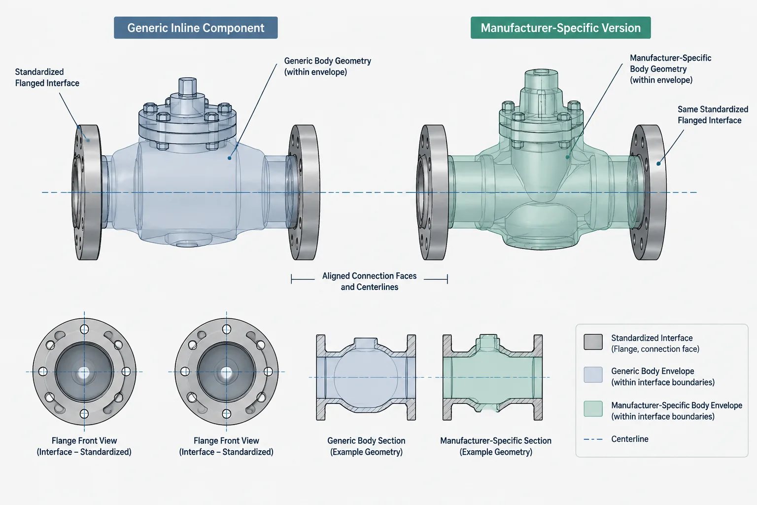
Deciding whether piping CAD geometry can be treated as generic requires more than recognizing a familiar component shape. The key question is whether the modeled feature is controlled by a dimensional standard, a project requirement, or the design of the selected product.
This guide explains how to distinguish reliable standard-based interfaces from manufacturer-dependent envelopes, document preliminary geometry, and prevent placeholder components from being mistaken for approved product data.
A piping component may look standardized without being fully interchangeable. Pipe, fittings, flanges, valves, strainers, instruments, and specialty items can all have nominal descriptions, but those descriptions do not necessarily define every dimension needed for layout, fabrication, operation, or maintenance.
This distinction matters in CAD. A generic component may be adequate for an early routing study, while the same representation may be unsafe to use for a fabrication drawing or equipment interface. Designers therefore need to know which dimensions come from an applicable dimensional standard, which are controlled by the project specification, and which must be obtained from a selected manufacturer.
What Is a Standard Dimension?
A standard dimension is a dimension defined through an applicable industry document for a particular component category, size, class, type, or end connection. Depending on the component, standardized information may cover dimensions such as:
- Pipe outside diameter and nominal wall designation
- Fitting center-to-end or end-to-end dimensions
- Flange outside diameter, thickness, facing, and bolt pattern
- Selected valve face-to-face or end-to-end dimensions
- Specified preparation of welding, threaded, socket, or flanged ends
Standardized does not mean universal. A dimension is only meaningful when the component description has been matched to the correct standard, size system, pressure designation, material or construction category, and connection type. Similar-looking components governed by different documents may not share the same geometry.
It is also important to avoid treating a dimensional standard as a complete product definition. Dimensional documents typically do not establish every feature of a manufacturer’s casting, forging, operator, accessory, or internal construction.
What Is a Manufacturer Dimension?
A manufacturer dimension comes from the actual product selected for the project. It may be shown on a certified drawing, product data sheet, dimensional catalog, submittal, or vendor-supplied model. These dimensions often define features that are not standardized or are allowed to vary within the product design.
Typical manufacturer-dependent information includes:
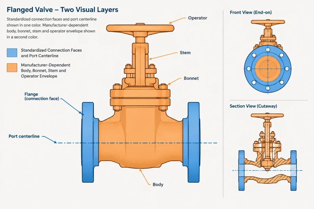
- Valve body envelope and bonnet height
- Handwheel, lever, gearbox, or actuator geometry
- Drain, vent, lubrication, and accessory locations
- Strainer body shape and screen-removal clearance
- Instrument connection positions and transmitter envelopes
- Expansion joint hardware and restraint arrangements
- Specialty coupling, dismantling joint, and proprietary connection geometry
- Maintenance withdrawal paths and recommended access zones
Two products may use the same nominal size, pressure class, and end connection while having different overall envelopes. Even when their connecting faces can occupy the same locations, their operators, bodies, fasteners, or maintenance requirements may interfere with nearby piping or structure.
Generic Does Not Mean Approximate
A generic CAD component should represent known design intent without pretending that an unselected product has been fully defined. It can still use accurate standard-based connection points and controlling dimensions. The uncertainty should be limited to features that genuinely depend on product selection.
For example, a generic flanged valve may have controlled port locations and an applicable face-to-face dimension while using a conservative placeholder envelope for its body and operator. The model status should make clear that the final envelope and accessory arrangement require vendor confirmation.
An arbitrary shape copied from another project is different. Unless its dimensional basis is known, it should not be treated as a reliable generic component.
Which Source Should Control?
The controlling source depends on the project and component. A practical hierarchy begins with project requirements rather than with whichever CAD block is easiest to find.
| Information source | Typical role | Important limitation |
|---|---|---|
| Project piping specification | Defines permitted component types, materials, ratings, ends, and other project rules | May reference dimensions without reproducing them |
| Applicable dimensional standard | Provides standardized geometry for the defined component category | Does not necessarily define the complete product envelope |
| Approved manufacturer data | Defines the selected product, accessories, interfaces, and actual envelope | Must match the exact model and configuration being purchased |
| Project component catalog | Connects CAD geometry and properties to approved project selections | Can become outdated or incorrectly mapped |
| Legacy drawing or model | Provides historical context and possible existing conditions | Should not be assumed correct without verification |
If sources conflict, the discrepancy should be resolved rather than silently averaged or adjusted in the model. A catalog description, CAD symbol, purchase description, and vendor drawing should identify the same component configuration.
Components Commonly Suitable for Standard-Based Geometry
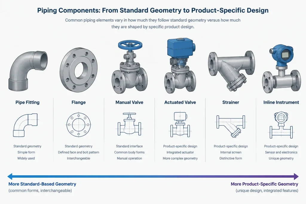
Many common pipe, fitting, and flange representations can be built primarily from recognized standard dimensions when the correct component definition is known. This is useful for routing, spool development, interference checks, and drawing production.
However, suitability still depends on the intended deliverable. A simplified elbow may be sufficient for a routing model, but a fabrication detail may need end preparation, tangent control, or weld information. A flange model may accurately represent the connecting face and bolt circle while omitting small manufacturing features that do not affect layout.
The model should contain enough geometry to support its purpose, but added detail should not imply unsupported precision.
Components That Usually Need Product-Specific Verification
Valves are a common source of confusion. Some valve end-to-end dimensions may follow a recognized dimensional series, but the overall body, bonnet, stem, operator, actuator, and accessory arrangement can remain manufacturer-dependent. A model that fits between two flanges may still clash with a platform or be impossible to operate.
Product-specific verification is especially important for:
- Actuated valves and packaged control valves
- Strainers requiring basket or screen removal
- Steam traps and assembled trap stations
- Flexible connectors and expansion joints
- Specialty inline equipment
- Flowmeters and instrument assemblies
- Proprietary couplings and mechanical connectors
- Components with liners, internal sleeves, or unusual flange arrangements
For these items, connection locations are only part of the interface. Weight, center of gravity, support needs, access, orientation restrictions, cable or tubing connections, and maintenance movement may also affect the layout.
A Practical CAD Workflow
1. Define the component before selecting geometry
Confirm the nominal size, end connections, pressure or class designation, material requirements, component type, and applicable project specification. Do not select a model based only on a familiar filename or visual similarity.
2. Record the dimensional basis
Store a source or status field with the component record. Useful statuses include standard-based, preliminary vendor envelope, approved vendor data, and field verified. The goal is to let reviewers understand what the geometry represents.
3. Separate connection geometry from envelope geometry
Ports, flange faces, weld ends, and component centerlines should be controlled independently from bodies, operators, and maintenance envelopes. This allows product-specific geometry to be updated without shifting established piping interfaces unnecessarily.
4. Model uncertainty visibly
When a vendor has not been selected, use a clearly identified placeholder or conservative envelope. Avoid modeling detailed ribs, fasteners, actuators, or accessories that could be mistaken for approved product data.
5. Replace placeholders systematically
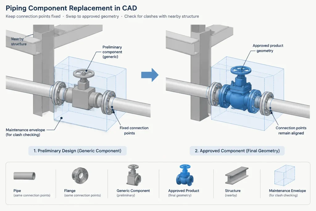
When approved information arrives, update the component through the project catalog or controlled library. Recheck connected piping, supports, access, structure, insulation, and removal paths. Replacing a block is not complete until affected interfaces have been reviewed.
6. Preserve the source with the revision record
The final model should be traceable to the information used to create it. If a vendor drawing changes, the related CAD component and affected drawings should be included in revision review.
Common Failure Modes
- Assuming nominal size defines the envelope: Nominal size identifies a size category, not every body or operator dimension.
- Using one valve model for every type: Gate, globe, check, ball, butterfly, and control valves can have substantially different shapes and access needs.
- Scaling a component: Uniform scaling does not reproduce valid connection geometry, wall thickness, bolt patterns, or face-to-face dimensions for another size.
- Mixing dimensional series: A replacement component may have the correct description but a different end-to-end series or connection arrangement.
- Ignoring accessories: Limit switches, solenoids, positioners, chain wheels, gearboxes, and tubing can control the actual clearance requirement.
- Treating downloaded CAD as approved data: A model’s origin, configuration, units, and dimensional basis must be checked before project use.
Review Questions Before Issuing a Drawing
- Is the component generic, selected, approved, or field verified?
- Which source controls its connection dimensions?
- Which parts of its envelope remain manufacturer-dependent?
- Does the modeled end connection match the piping specification?
- Have operator movement and maintenance removal been checked?
- Will a later vendor-model replacement preserve the established ports?
- Are drawings and material records linked to the same component definition?
The Key Distinction
Standard dimensions establish repeatable interfaces and common dimensional relationships. Manufacturer dimensions define the actual product within and beyond those interfaces. Good piping CAD practice uses both at the appropriate design stage.
A generic model is valuable when its basis and limitations are clear. A product-specific model is valuable when it matches the exact selected configuration. Problems arise when preliminary geometry is presented as approved, or when detailed-looking CAD is trusted without checking its source. Keeping dimensional authority visible helps protect layout quality, purchasing consistency, fabrication fit-up, and future component replacement.
How to Classify Geometry During Model Review
A practical review separates each component into functional layers rather than labeling the entire model as either generic or manufacturer-specific. This makes it easier to identify what can remain stable and what must change after product selection.
Connection geometry
This layer includes connecting faces, ends, ports, centerlines, and other features that establish the component’s relationship to adjoining piping. It may be standard-based when the complete component definition and applicable dimensional basis are known. It should not be inferred from appearance alone.
Physical envelope
The body, bonnet, operator, actuator, accessories, fasteners, and other projecting features define the occupied space. These features frequently depend on the manufacturer and selected configuration, even when the connection geometry follows a recognized dimensional series.
Operating and maintenance space
Required access is not necessarily part of the solid component body. Lever travel, handwheel access, removable elements, actuator service space, and instrument access may need separate clearance envelopes. These zones should remain distinguishable from permanent equipment geometry.
Identification and status data
The model record should identify the component definition, geometry source, approval status, and unresolved information. A detailed appearance is not a substitute for traceability. Reviewers need to know whether they are seeing a standard-based representation, a preliminary vendor envelope, approved product geometry, or field-verified conditions.
Criteria for Treating a CAD Component as Generic
A generic representation is most defensible when its use is limited to features supported by known requirements. Before accepting it, confirm that:
- The component category and end connections are unambiguous.
- The dimensional basis matches the project specification and component description.
- Standard-controlled features are separated from product-dependent features.
- Unknown envelopes and clearances are visibly identified as preliminary.
- The component can be replaced without concealing changes to connected piping or nearby objects.
- The issue status of the drawing is consistent with the maturity of the model data.
If these conditions cannot be established, the geometry should be treated as a reference placeholder rather than a dependable generic component.
Managing Change After Manufacturer Selection
Vendor confirmation is not merely a drafting update. Changing a preliminary component can affect connected pipe, supports, structural clearances, insulation, access, controls, tubing, and removal paths. The replacement should therefore be reviewed as an interface change.
A useful comparison focuses on connection locations, occupied envelope, orientation, accessories, support conditions, and maintenance movement. Any difference that affects another discipline or issued drawing should enter the project’s normal revision and coordination process.
Frequently Asked Questions
Can nominal size be used to select a generic CAD model?
Nominal size alone is not enough. The component type, end connection, dimensional series, pressure or class designation, construction category, and project specification may all affect which geometry applies.
Can a valve be generic if its face-to-face dimension is standardized?
Only part of the valve may be generic. The connecting faces and end-to-end relationship may be standard-based, while the body, bonnet, stem, operator, actuator, and accessories still require product-specific verification.
Is detailed downloaded CAD more reliable than a simplified block?
Not necessarily. Visual detail does not prove that the model matches the required component. Its source, units, configuration, dimensional basis, and approval status must be verified before use.
Should an unselected component use a conservative envelope?
A conservative placeholder can support preliminary coordination when its basis and status are clearly documented. It should not be presented as approved product geometry, and it must be replaced or confirmed when selected-product information becomes available.
What should remain fixed when replacing a placeholder?
Verified piping interfaces should remain controlled unless approved information requires a change. The replacement process should compare ports, faces, centerlines, orientation, envelope, accessories, supports, and maintenance needs rather than assuming the new model is interchangeable.
Can a manufacturer model be used without checking the project component catalog?
No. The manufacturer geometry must correspond to the same product configuration represented by the project specification, material records, purchasing information, and CAD catalog entry.