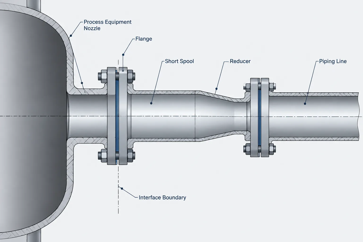
An equipment nozzle size mismatch must be resolved as a controlled piping interface, not hidden by overlapping geometry or a resized CAD symbol. The nozzle, mating connection, transition components, line size, and supply boundary should remain identifiable in both the model and associated material data.
This guide explains how to coordinate reducers, flanges, valves, spools, and vendor-supplied items when an equipment connection differs from the adjoining process line. It also highlights the checks needed to keep the arrangement consistent across equipment drawings, piping models, isometrics, and material reports.
An equipment nozzle and its connecting process line do not always have the same nominal size. A pump connection may be smaller than the connected header, a vessel nozzle may be larger than the branch line, or a packaged unit may use a connection selected by the vendor rather than by the piping designer. These conditions are common, but they require more than placing a reducer somewhere near the equipment.
An equipment nozzle size mismatch affects flange compatibility, reducer orientation, valve placement, piping flexibility, equipment loads, access, drainage, and fabrication dimensions. The CAD model must show a buildable transition while preserving the distinction between vendor-owned equipment geometry and project-owned piping.
What a nozzle size mismatch actually means
A nozzle size mismatch exists when the nominal size of the equipment connection differs from the nominal size of the adjoining piping system. The mismatch does not mean that unlike flanges can be bolted together or that a mating component can simply be scaled to fit.
The immediate connection at a flanged nozzle normally needs a compatible mating flange or flanged component. The change to the process-line size occurs through a deliberate transition, such as a reducer, reducing fitting, or specially designed component permitted by the project specification.
Keep the following items separate in the model and component data:
- Nozzle nominal size: the connection size established by the equipment design or vendor data.
- Nozzle connection type: the flange, weld end, thread, clamp, or other interface provided on the equipment.
- Line nominal size: the size assigned to the connected process line.
- Transition component: the fitting or assembly that changes from one nominal size to another.
- Interface location: the point at which responsibility changes between the equipment package and field or shop piping.
Do not force the line size onto the nozzle
A common modeling error is to route the process line at its assigned size directly to a smaller or larger nozzle, leaving the software connection unresolved or concealing the mismatch inside overlapping geometry. Another error is to scale a flange block until its outside shape appears to match the nozzle.
Neither approach defines a real connection. Scaling changes graphic size but does not establish the correct bore, flange facing, bolt pattern, hub geometry, component length, or material description. A visually connected model can therefore produce an incorrect bill of material and an unbuildable isometric.
Model the nozzle at the documented nozzle size. Model the mating piping component at the compatible connection size. Then represent the size transition explicitly.
Where should the reducer be placed?
The reducer does not always belong directly against the equipment nozzle. Its location should reflect operation, maintenance, hydraulic intent, fabrication, and available space.
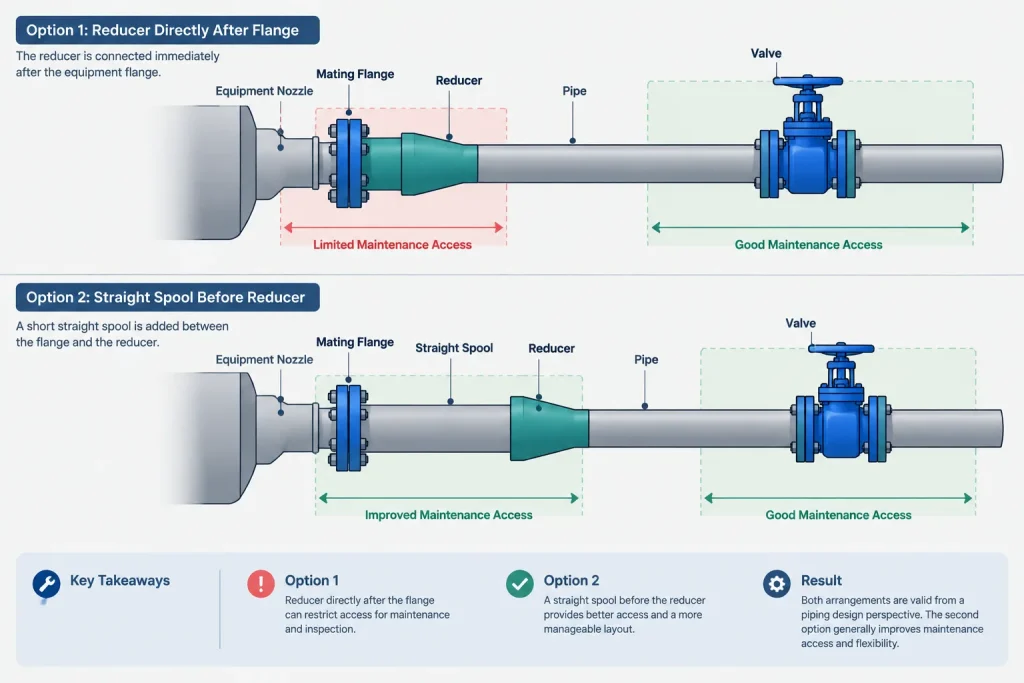
Reducer immediately after the mating flange
Placing the reducer close to the nozzle can create a compact arrangement. This may be useful where space is limited, but the designer must still check flange bolting access, weld access, insulation, nearby supports, and the ability to remove equipment or adjacent piping.
A compact connection can also increase stiffness near the nozzle. The resulting load effect cannot be judged from appearance alone; it may require coordination with piping stress analysis and the equipment supplier.
Straight spool between the nozzle and reducer
A straight spool can provide room for bolting, field fit-up, inspection, supports, instruments, or equipment removal. It can also move the transition away from a congested nozzle zone. However, the added spool length changes the piping geometry and may affect flexibility, support reactions, drainage, and the equipment maintenance envelope.
Reducer located beyond a valve
In some arrangements, a valve is installed at the nozzle size and the reducer is placed farther downstream. In others, the piping transitions first and the valve is selected at the line size. These arrangements are not equivalent.
Valve size and location can affect isolation function, flow characteristics, weight, operator access, replacement space, and cost. The CAD designer should not choose the sequence solely to simplify routing. Confirm the intended arrangement with the process, mechanical, equipment, and piping disciplines as applicable.
Concentric or eccentric transition?
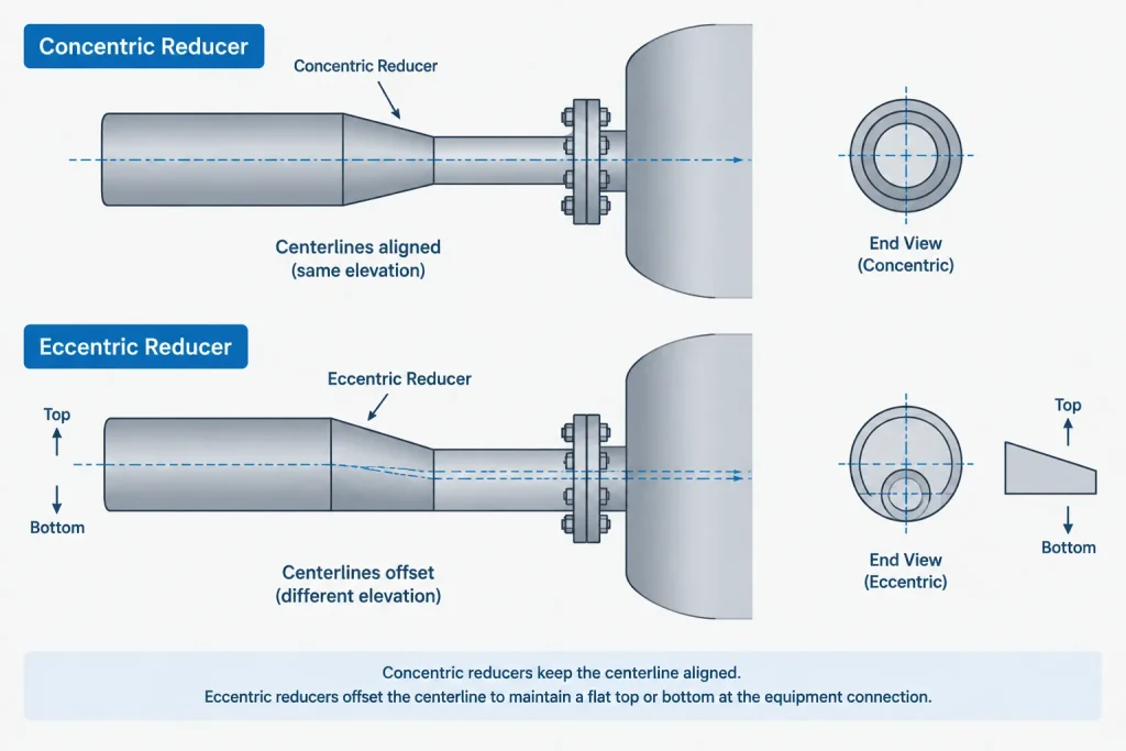
The choice between concentric and eccentric reducers depends on service and orientation, not merely on which shape fits more easily.
A concentric reducer keeps the larger and smaller end centerlines aligned. An eccentric reducer offsets those centerlines and can maintain a selected top or bottom elevation. That offset can be important where the layout must avoid vapor pockets, support drainage, preserve an equipment suction arrangement, or maintain a defined pipe elevation.
The model should communicate eccentric reducer orientation unambiguously. A correct fitting with an undocumented rotational orientation may still be installed incorrectly. Use the project’s established notes, orientation symbols, isometric graphics, or model properties rather than relying only on a subtle three-dimensional shape.
Flange and connection compatibility still governs
Nominal size is only one part of the nozzle interface. Before treating two components as connectable, verify the relevant connection characteristics from controlled project and vendor information. Depending on the connection, these may include:
- Connection type and nominal size
- Flange type, facing, and pressure designation
- Bore or inside profile at the interface
- Material and piping specification requirements
- Gasket and bolting arrangement
- End preparation for welded connections
- Vendor-supplied companion flange or transition piece
A line specification may contain a suitable reducer but not the correct mating flange for a vendor nozzle. Conversely, the equipment package may include a companion component that must be represented as vendor supply rather than counted again in the piping material takeoff.
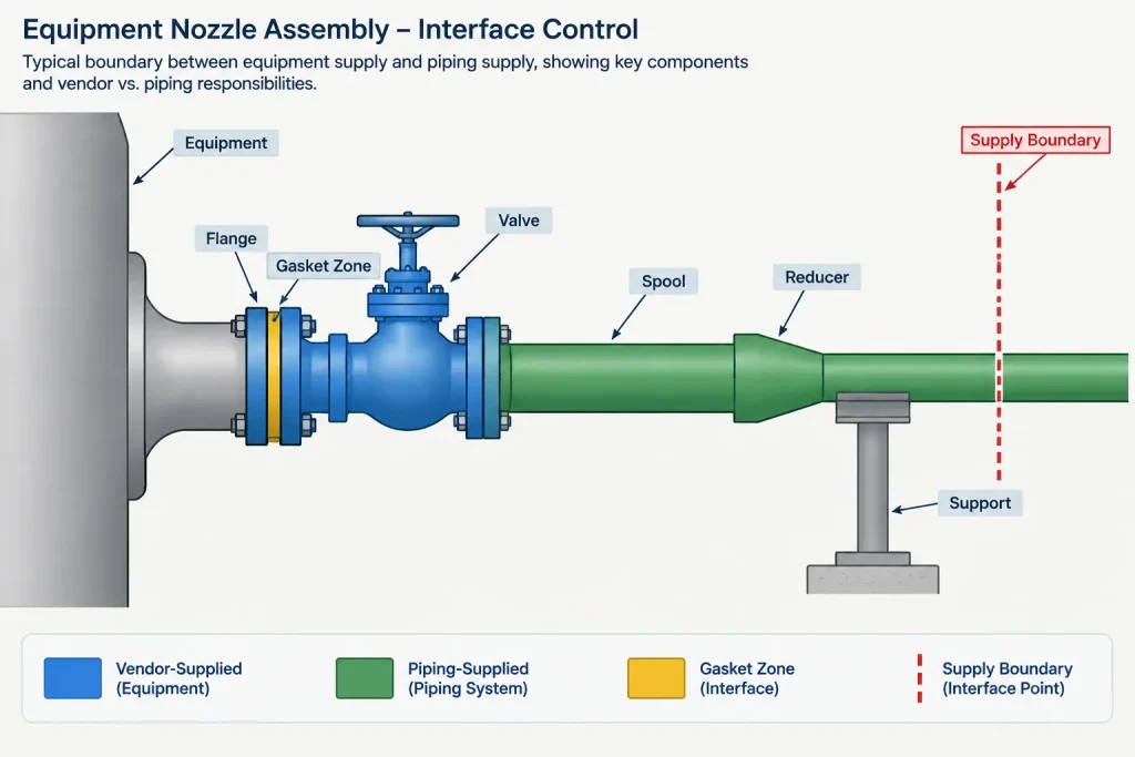
Control the vendor-to-piping boundary
The physical flange face is often used as an equipment interface, but the contractual supply boundary may be elsewhere. A vendor package might include a mating flange, short spool, valve, flexible connector, or reducer. The piping model must distinguish physical connectivity from supply responsibility.
| Information | Typical source | CAD use |
|---|---|---|
| Nozzle size, type, rating designation, and orientation | Controlled equipment or vendor drawing | Defines the equipment connection |
| Process line size and service | Approved process documentation and line data | Defines the connected piping system |
| Permitted transition components | Project piping specification | Controls component selection |
| Supply split | Purchase documents and interface schedule | Prevents missing or duplicated materials |
| Allowable nozzle loads | Equipment data and engineering review | Supports flexibility and load evaluation |
If vendor data is preliminary, identify the nozzle geometry as provisional according to the project’s status convention. Do not convert an estimated connection into apparently final model geometry without recording the assumption.
CAD checks around the transition
A nozzle transition should be reviewed as an assembly rather than as an isolated reducer. Useful checks include:
- Face alignment: Confirm that mating flange faces are coincident and correctly oriented.
- Component sequence: Verify the intended order of flange, spool, valve, reducer, and branch components.
- Centerline change: Account for any eccentric offset instead of forcing both pipe runs onto one centerline.
- Maintenance space: Check equipment withdrawal, valve removal, bolt extraction, and access to operators.
- Support arrangement: Avoid unintentionally transferring excessive nearby piping weight or restraint to the nozzle.
- Drainage and venting: Review whether the transition creates a local high point or low point.
- Insulation envelope: Include the outside envelope where insulation or removable covers affect clearance.
- Material reporting: Confirm that vendor-supplied and piping-supplied items are classified correctly.
A practical modeling workflow
Begin with the latest controlled equipment nozzle information. Place the nozzle using its documented location, projection, orientation, size, and connection type. Route the process line using the assigned line size rather than modifying it to hide the mismatch.
Next, select a permitted transition arrangement and place each component as a separate, correctly identified item. Check the resulting geometry against access, support, hydraulic, stress, and fabrication needs. Where more than one arrangement is possible, keep alternatives clearly marked as studies until the responsible disciplines approve the design basis.
Finally, reconcile the model with the equipment drawing, piping specification, line data, isometric, and material report. The transition should tell the same story in geometry and data: what connects to the nozzle, where the size changes, how the reducer is oriented, and who supplies each item.
Key takeaway
An equipment nozzle size mismatch is an interface problem, not just a fitting-placement problem. Accurate CAD work preserves the actual nozzle connection, shows an explicit and permitted size transition, and coordinates the surrounding flange, valve, spool, supports, and maintenance space. When vendor information is incomplete, document the uncertainty rather than disguising it with generic or scaled geometry.
Interface records should match the physical assembly
The completed model should allow a reviewer to follow the connection from the equipment nozzle into the process line without inferring where the size change or responsibility boundary occurs. Component descriptions, connection data, reducer orientation, and ownership classifications should support the geometry rather than contradict it.
This is especially important when the physical connection point and the commercial supply boundary are different. A component may be attached near the equipment while still belonging to the piping scope, or it may appear within the piping arrangement while remaining part of the vendor package.
Review the transition across deliverables
- Equipment drawing: Confirm the nozzle location, projection, orientation, nominal size, and connection description.
- Piping model: Confirm that every physical component in the transition is represented with the intended sequence and orientation.
- Isometric drawing: Make sure the size change, eccentric orientation, field connection, and supply notes are understandable to fabrication and construction personnel.
- Material report: Check that project-supplied items are included and vendor-supplied items are not duplicated.
- Interface register: Record unresolved vendor information, responsibility boundaries, and required follow-up.
Managing changes during design development
Nozzle information can change as equipment data develops. When that happens, updating only the equipment model is insufficient. The connected flange, spool, valve, reducer, supports, insulation envelope, and nearby access space may also require review.
A disciplined change review should identify which deliverables were based on the earlier nozzle information and whether fabrication or procurement data has already been released. Retaining a visible status for provisional geometry helps prevent an assumed connection from being treated as approved.
What a model review should demonstrate
A successful review should demonstrate that the modeled connection is physically compatible, permitted by the project piping requirements, accessible for assembly and maintenance, and correctly assigned to the responsible supply scope. It should also show that eccentric offsets, valve access, equipment removal paths, supports, and potential nozzle loading concerns have not been obscured by a visually compact arrangement.
Frequently asked questions
Can a piping flange be scaled to match a different equipment nozzle size?
No. Graphic scaling does not create the correct flange connection, bore, facing, bolt arrangement, component description, or material record. Use a compatible mating component and an explicit size transition.
Must the reducer be installed directly at the equipment nozzle?
Not necessarily. Its location depends on the approved arrangement and considerations such as bolting access, weld access, valve sequence, equipment maintenance, drainage, supports, flexibility, and fabrication.
Who determines whether a concentric or eccentric reducer is required?
The selection should follow the service and layout requirements established by the responsible engineering disciplines and project specifications. The CAD model should clearly show the approved fitting type and, for an eccentric reducer, its rotational orientation.
What if the vendor supplies a companion flange or reducer?
Represent the supplied item as needed for physical coordination, but classify it according to the documented supply boundary. This prevents the item from being omitted from the assembly or duplicated in the piping material takeoff.
How should preliminary nozzle information be modeled?
Use the project convention for provisional or unapproved data, retain the source and assumption in the interface record, and avoid presenting estimated geometry as final. Recheck connected piping when controlled vendor information is issued.
Does a connected-looking CAD model prove flange compatibility?
No. Visual contact confirms only that geometry appears to meet. Compatibility must be checked using controlled connection information, including nominal size, connection type, facing or end preparation, pressure designation, material requirements, gasket arrangement, and bolting requirements as applicable.