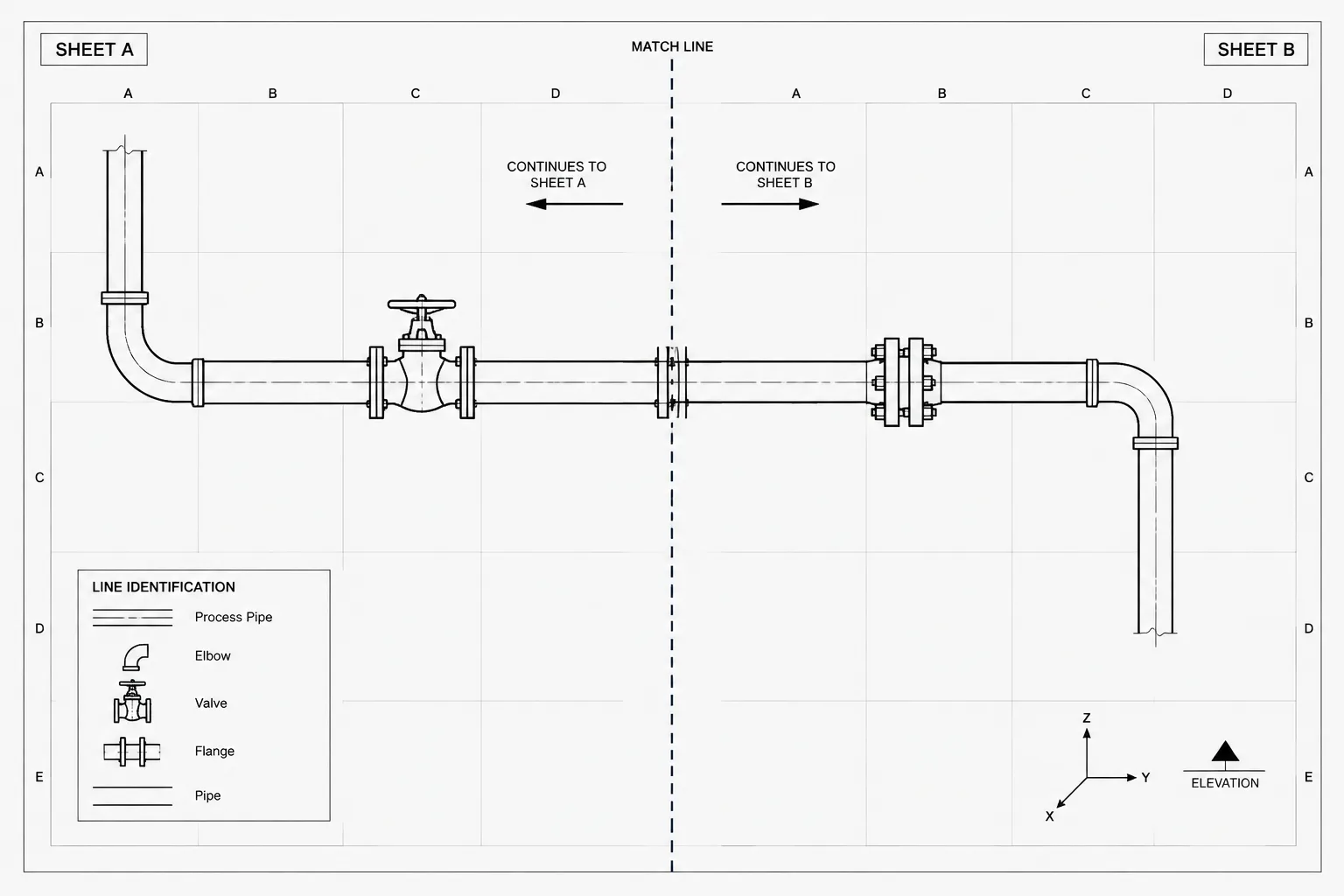
Piping match lines and continuation references allow a route to remain traceable when its graphical representation is divided among sheets, views, CAD files, or model areas. The key drafting task is not merely showing that the pipe continues, but preserving enough information to confirm its identity, location, orientation, and destination.
This guide explains how match lines differ from physical piping interfaces, what information supports a reliable continuation, and how designers can review adjoining drawings for geometric and documentation conflicts.
Large piping systems rarely fit clearly on one drawing sheet. A route may cross several plan areas, continue onto another elevation, or pass from a unit drawing into an adjacent rack drawing. Piping match lines and continuation references provide the control needed to divide that continuous system without losing its identity, location, or connectivity.
A match line is not simply a convenient place to crop a view. It is a documented boundary between drawing areas. When the information on both sides is coordinated correctly, a reader can follow the pipe across sheets and reconstruct the route without guessing. When it is not, the same boundary can conceal duplicated pipe, missing fittings, conflicting dimensions, or disconnected CAD geometry.
What a piping match line represents
A match line identifies where a drawing view stops and where the corresponding representation continues. The physical pipe does not stop at that line. Only its presentation on the current sheet ends.
Depending on the drawing system, the boundary may separate:
- Adjacent areas on piping general arrangement drawings
- Plant units, modules, buildings, or pipe rack segments
- Different drawing sheets within the same area
- Plan views and related elevation views
- New work and an externally controlled package
- Different CAD files, model references, or design responsibilities
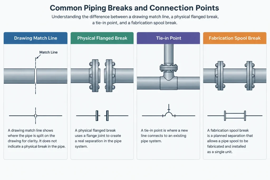
The line should therefore be treated as a drawing-control feature rather than a piping component. It does not create a flange, weld, coupling, or field joint unless a separate design instruction identifies one at that location.
Match line, continuation mark, and interface point
Several boundary-related terms are commonly used, but they do not always mean the same thing.
| Term | Primary purpose | What it does not automatically mean |
|---|---|---|
| Match line | Defines the shared edge between adjoining drawing areas or views | A physical break in the pipe |
| Continuation reference | Directs the reader to the drawing, view, or area where the route continues | A fabrication joint or tie-in |
| Battery limit or unit boundary | Identifies an organizational or contractual interface | Necessarily the edge of a drawing sheet |
| Tie-in point | Identifies a controlled connection to existing work or another scope | Merely a graphic continuation |
| Spool break | Divides fabrication or erection assemblies | A drawing-area boundary |
These conditions can occur at the same location, but one should not be inferred from another. For example, a pipe may cross a match line continuously while its nearest field weld is located elsewhere. Conversely, a tie-in may appear well inside a drawing area rather than at its edge.

Information needed at a continuation
A useful continuation reference gives the reader enough information to find and verify the other side. The exact drafting format depends on project procedures, but the control information commonly includes:
- The destination drawing or model area
- The destination sheet, view, or zone when applicable
- The piping line identifier
- The continuation direction
- A coordinate, grid reference, or other location control
- The elevation basis needed to confirm vertical position
- Any applicable specification, service, or scope transition
Not every item has to be repeated beside every crossing. The important point is that the drawing set must provide an unambiguous path to the continuation and a reliable way to confirm that both representations describe the same pipe.
Line identity
The line number or other system identifier should remain consistent across an ordinary drawing split. A change in the displayed line identity should correspond to a defined engineering or documentation reason, not merely a change of sheet.
Position and elevation
Matching line identity alone is insufficient. Two drawing segments can carry the same identifier and still fail to meet geometrically. Coordinates, structural grids, equipment references, or controlled dimensions help confirm horizontal position. Elevation notation establishes whether the stated value applies to the pipe centerline, bottom, top, or another defined reference.
Direction and orientation
The continuation should be readable even when adjoining drawings use different sheet orientations. North arrows, view titles, coordinate directions, and directional continuation symbols prevent the reader from assuming that the right side of one sheet automatically joins the left side of another.
Reciprocal references between drawings
A continuation works best as a two-way reference. Drawing A should direct the reader to Drawing B, and Drawing B should direct the reader back to Drawing A. This reciprocal arrangement supports checking and makes navigation easier during design, construction, and later maintenance.
One-way references are vulnerable to drawing renumbering and area changes. A destination drawing may show the incoming pipe but fail to identify its source, leaving the reviewer to search by line number. Reciprocal references also expose coordination errors: if each side points to a different destination, the drawing register or the reference callout needs correction.
How match lines should interact with CAD geometry
In a coordinated model workflow, the pipe itself is ideally continuous in the design model even when it appears on several drawing sheets. Sheet viewports, clipping boundaries, external references, or area-based drawing extraction then control its presentation.
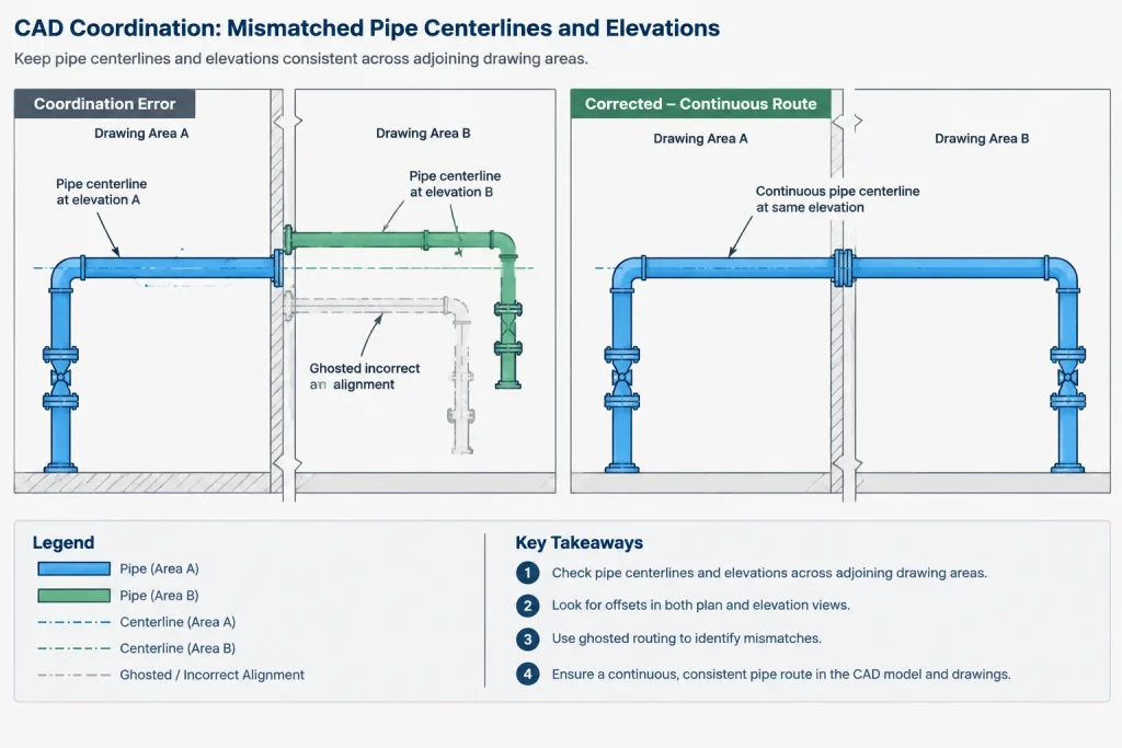
If separate CAD files contain independently drawn portions of the route, the interface requires additional care. Both files should use the same coordinate basis, units, orientation, and elevation datum. Designers should avoid manually shifting copied geometry merely to make a sheet look aligned. A visually convincing continuation can still be spatially wrong.
Duplicating a short length of pipe on both drawings may improve visual context, but duplicated graphics must not become duplicate model objects or duplicate material quantities. Projects that use overlap zones should define which file owns the physical component data and which representation is reference-only.
Choosing a practical match-line location
A good drawing boundary is easy to recognize and does not obscure critical piping detail. Useful locations often follow structural grids, area limits, module edges, or other stable project references.
Where possible, avoid placing a boundary through:
- A valve, fitting, flange joint, or specialty item
- A congested branch connection
- An equipment nozzle interface
- A dimensioned offset or elevation change
- A support assembly that must be understood as a whole
- A region containing several closely spaced line crossings
These locations are not universally prohibited, but they increase the chance that notes, dimensions, tags, or component relationships will be split between sheets. Moving the graphical boundary does not necessarily change the physical design, so drafting clarity can often be improved without rerouting the pipe.
Common match-line errors
Mismatched coordinates
The two sheets show the same line identifier but place the crossing at different coordinates or grids. This often results from uncontrolled file origins, stale references, or manual drafting changes.
Conflicting elevations
One side uses centerline elevation while the other uses bottom-of-pipe elevation without clearly stating the basis. The values may look inconsistent even when the geometry is correct, or they may hide a genuine vertical mismatch.
Missing destination information
A line ends at a boundary with a generic continuation arrow but no drawing, area, or view reference. The reader can recognize that the pipe continues but cannot locate it efficiently.
Components divided across sheets
A valve body appears on one drawing while its operator, tag, or maintenance envelope appears on another. Neither sheet then communicates the complete layout condition.
Revision on only one side
A route is moved on one drawing, but the adjoining sheet retains the previous crossing location. This is especially common when files have different owners or revision schedules.
A practical CAD review workflow
Match-line checking should be performed as an interface review, not only as a drafting cleanup task. A practical sequence is:
- Identify every pipe, duct, conduit, or other routed item crossing the boundary.
- Confirm that each crossing has a readable destination reference.
- Open the destination drawing rather than relying on its title alone.
- Compare line identity, size notation, service, and specification information.
- Check coordinates, grid position, route direction, and elevation basis.
- Verify that components near the boundary are neither omitted nor duplicated.
- Confirm that drawing references are reciprocal.
- Review revision status on both sides of the interface.
- Check whether material reports or quantities count overlapping graphics correctly.
Automated model comparison can help find disconnected geometry, but it does not replace document review. Software may confirm that two pipe segments meet spatially while missing a wrong continuation note, inconsistent line identifier, or obsolete destination sheet.
Match lines as drawing-control tools
Well-managed piping match lines make a large drawing set behave like one coordinated representation. Their purpose is to preserve continuity across the artificial boundaries created by sheets, files, areas, and project scopes.
The most reliable practice is to control three things together: identity, geometry, and reference. The line identifier establishes what continues, coordinates and elevations establish where it continues, and reciprocal callouts establish where the reader should look next. When all three agree, drawing boundaries remain useful organizational tools instead of becoming sources of field uncertainty.
Using match-line information during drawing review
A reviewer should treat each match-line crossing as a controlled handoff. The outgoing representation and the incoming representation must describe the same route, while each drawing remains clear about its own scope. This requires coordination between drawing annotations, referenced CAD geometry, model ownership, and revision control.
Separate presentation boundaries from design boundaries
A sheet edge or clipped view changes how the route is presented, not how the piping is constructed. Any physical connection, fabrication break, scope interface, or tie-in must be identified through its own established notation. Keeping these concepts separate prevents a continuation symbol from being mistaken for a component or joint.
Define which source controls the geometry
Where adjoining files overlap, the project workflow should identify which model or file owns the piping objects. The other representation may provide context, but it should not create competing component data. This distinction is important when drawings, reports, and material information are produced from different CAD sources.
Review interfaces when either side changes
A revision near a match line should trigger a check of the adjoining drawing, even when that drawing does not otherwise appear affected. Route movement, annotation changes, renamed areas, and revised view limits can invalidate a continuation reference without changing the pipe identifier.
Check the issued deliverable, not only the model
Continuous model geometry does not guarantee a usable drawing. Clipping can hide a fitting, annotation can overlap the boundary, or a callout can point to an obsolete destination. Final review should therefore include the plotted or published sheet representation as well as the underlying CAD model.
Frequently asked questions
Does a piping match line indicate a physical pipe joint?
No. A match line normally marks the boundary of a drawing area or view. A weld, flange, coupling, tie-in, or other physical connection requires separate design documentation.
Should the line identifier change when piping crosses to another sheet?
An ordinary sheet transition does not by itself justify a new line identity. Any identifier change should reflect an established engineering or documentation condition rather than the graphical boundary alone.
Why should continuation references be reciprocal?
References in both directions make the route easier to trace and expose coordination problems. If the two sides do not point back to each other correctly, the drawing set may contain an outdated callout, area assignment, or destination reference.
Can overlapping pipe graphics appear on adjoining drawings?
Overlap may be used to provide context, but the workflow should distinguish reference graphics from the source that owns the actual piping objects. Otherwise, components or quantities may be duplicated.
What should be checked when a route changes near a match line?
Review the crossing location, route direction, elevation basis, line identity, destination callout, nearby components, and the revision status of both drawings. The published sheet should also be checked for clipping and annotation problems.
Is matching geometry enough to validate a continuation?
No. Geometry may connect while the annotation remains wrong. A complete review considers route identity, spatial position, drawing destination, scope information, and revision coordination together.