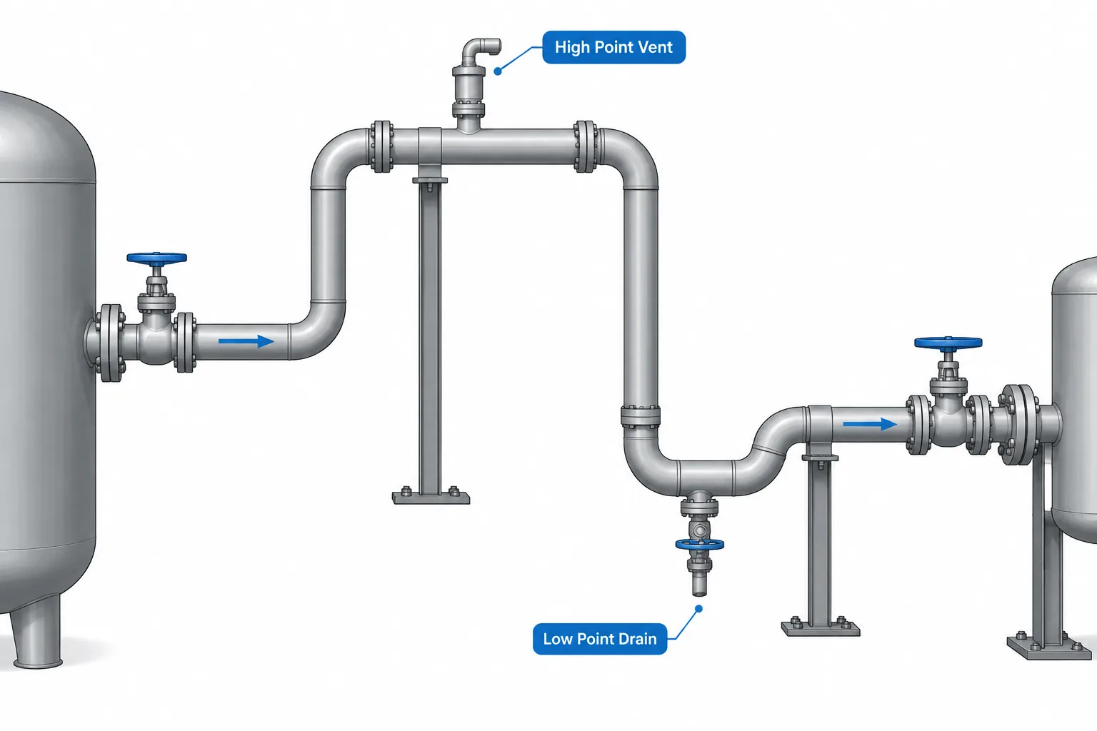
High-point vents and low-point drains in piping CAD require more than placing a small branch at an obvious elevation. The designer must evaluate the connected fluid path, isolation boundaries, operating condition, discharge destination, accessibility, and documentation status.
This guide explains how to recognize potential gas and liquid traps, distinguish permanent connections from temporary provisions, and coordinate the resulting design across the P&ID, piping model, isometric, and test documentation. Any proposed connection should be confirmed against the project piping specification, process intent, operating procedure, and safety requirements.
High-point vents and low-point drains are small connections with an important role in piping operation, commissioning, testing, and maintenance. Their locations may affect whether a line can be filled, emptied, vented, cleaned, or safely isolated. Because they often use small-bore components, however, they can be overlooked during early layout or represented too simply in a CAD model.
A geometric high or low point does not automatically require a permanent connection. The need depends on service, operating procedure, piping configuration, test strategy, and project requirements. The designer’s task is to identify potential trapping locations, confirm the intended function, and provide enough model and drawing information for the connection to be reviewed and fabricated correctly.
What High-Point and Low-Point Mean
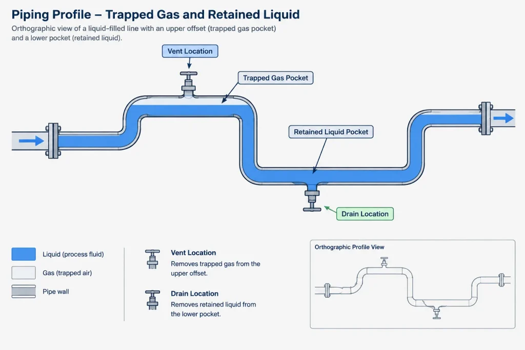
A high point is a locally elevated part of a piping system where gas or vapor may collect when liquid fills the line. A low point is a locally depressed part where liquid may remain when the line is drained or gas is introduced. These terms describe the geometry of the connected fluid path, not simply the highest or lowest component visible in one drawing view.
The relevant point may occur at an elbow, vertical offset, equipment nozzle, reducer, branch, valve cavity, or sloped-run transition. A location that appears level in plan may contain an elevation change that becomes clear only in a model or elevation view.
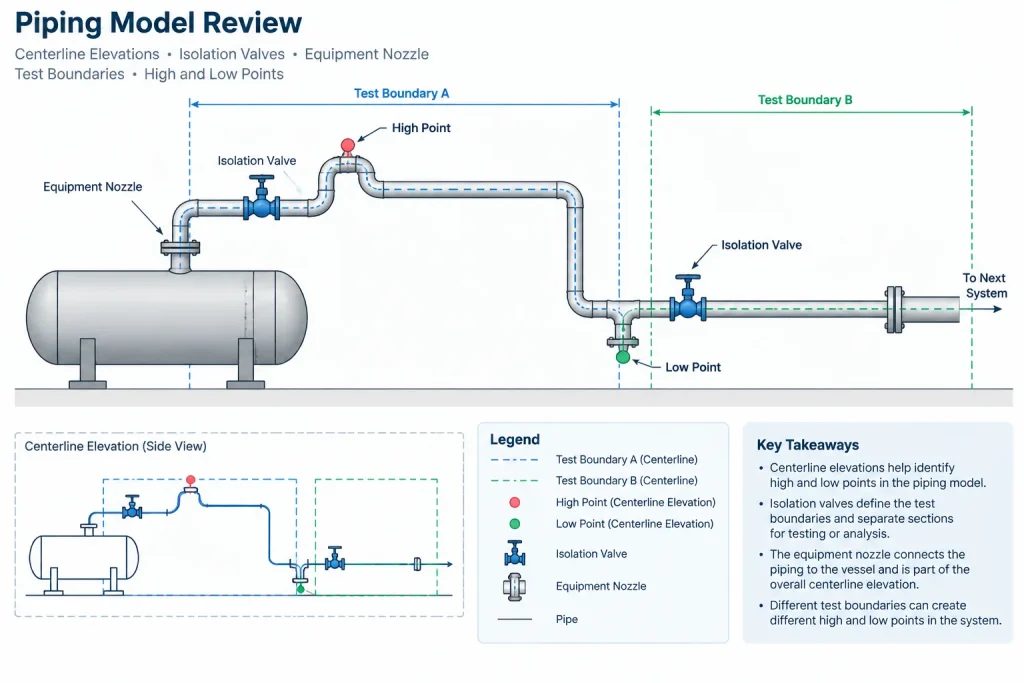
Designers should also consider the system boundary. A point may be locally high within one spool but may not be a system high point after that spool is connected to adjacent piping. Conversely, a route that looks continuously sloped may contain a hidden pocket at an equipment connection or specification break.
Vent and Drain Functions Are Not Interchangeable
The words vent and drain describe functions rather than a single standard assembly. A connection may be permanent, temporary, process-related, or intended only for a defined maintenance or test activity.
| Connection function | Typical purpose | Key CAD and documentation question |
|---|---|---|
| Process vent | Releases gas or vapor during normal or specified operation | Where does the discharge go, and how is it controlled? |
| Process drain | Removes liquid, condensate, or collected material | Is the receiving system identified and compatible with the service? |
| Startup or commissioning connection | Supports initial filling, flushing, purging, or air removal | Will the connection remain after commissioning? |
| Test vent | Allows trapped gas to escape while a test section is filled | Is it part of the permanent design or a temporary test provision? |
| Test drain | Allows removal of the test medium after testing | Can the defined test section actually empty through this location? |
| Maintenance connection | Supports equipment or line isolation, depressurization, or draining | Can personnel reach and operate it safely? |
A generic note such as “provide vent” is usually insufficient for coordinated design. The model and associated documents may need to distinguish the branch connection, valve, closure, discharge routing, and destination. The required detail depends on the project’s design stage and deliverables.
Finding Potential Traps in a CAD Model
High and low points should be reviewed along the full connected route rather than one drawing at a time. A useful review combines the P&ID, line list, piping model, equipment data, and intended operating or test boundaries.
Review the centerline profile
Trace the pipe centerline in the direction of flow and note every elevation change. Check vertical offsets, rolling offsets, nozzle approaches, rack transitions, road crossings, and changes required to avoid structures. Do not assume that a nominally horizontal run is truly level; the line may have an intentional slope.
Check the actual fluid boundary
Closed valves, blinds, check valves, equipment internals, and temporary isolation points can divide a line into separate fill or drain volumes. A vent located beyond a closed boundary cannot release gas from the isolated section. Likewise, a drain on the other side of an isolation point does not empty the trapped volume under review.
Examine components that create pockets
Valve bodies, eccentric transitions, inline instruments, strainers, and equipment connections may retain fluid even when the adjacent pipe centerline appears drainable. Simplified CAD geometry may not show the internal cavity, so component information and operating orientation must be checked.
Review all operating states
A route that drains during normal operation may behave differently when isolated for maintenance. Flow direction can change during startup, cleaning, regeneration, or temporary operation. The relevant high point or low point therefore depends on the condition being evaluated.
Locating the Branch Connection
Once a functional need is confirmed, the branch should be located where it can communicate with the trapped phase. A vent intended to release gas is generally connected at an effective upper location, while a drain intended to remove liquid is generally connected at an effective lower location. The exact branch orientation and fitting arrangement must follow the project piping specification and service requirements.
Accessibility can compete with hydraulic effectiveness. Moving a drain to a convenient side position may leave liquid below the opening. Moving a vent down from the top of a line may leave a vapor pocket. If direct access is impractical, a routed connection may be considered, but that route introduces its own slope, support, clearance, and drainage questions.
Branch placement should also account for:
- pipe wall and branch connection requirements;
- insulation and removable insulation covers;
- valve handle or wrench access;
- discharge direction and personnel exposure;
- nearby platforms, walkways, steel, and cable trays;
- support for the small-bore assembly;
- vibration and susceptibility to accidental impact;
- space for plugs, caps, hoses, or temporary fittings where specified.
Open Discharge vs. Routed Connections
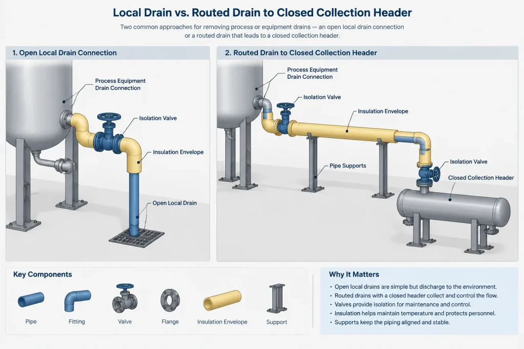
A vent or drain should not be assumed to discharge locally. The fluid may be hazardous, hot, cold, pressurized, flammable, corrosive, contaminated, or otherwise unsuitable for release near personnel or equipment. The process design must establish whether the connection terminates locally, uses a temporary hose, or routes to a closed collection, recovery, flare, vent, drain, or treatment system.
Routed connections require the same layout discipline as other piping. Their destination, slope, isolation, support, flexibility, and specification boundaries must be coordinated. A routed drain that rises before reaching its destination can create a new liquid pocket. A vent line with an unintended low point may collect condensate and stop functioning as expected.
How Much Geometry Should Be Modeled?
The required model detail depends on the connection’s design maturity and coordination importance. During early routing, a branch point and reserved clearance may be enough. Before fabrication deliverables are issued, permanent components normally need sufficient definition for material identification, orientation, accessibility, and interference review.
A useful CAD representation may include:
- the branch location and orientation on the main pipe;
- the specified branch fitting or connection type;
- valve body and operator envelope;
- closure or continuation point;
- routed discharge piping where applicable;
- insulation envelope and support features when relevant;
- connection tags or notes tied to project data.
A symbolic placeholder should not be mistaken for fabrication-ready geometry. If the final assembly has not been selected, its status should remain clear in the model and review documentation.
Drawing and Data Coordination
The P&ID usually communicates the functional intent, while the 3D model establishes physical location and orientation. Isometrics and spool drawings communicate fabrication and installation information. Test diagrams or packages may define temporary boundaries and test-specific connections. These documents should agree without being forced to show identical levels of detail.
During review, compare the connection across the available deliverables:
- Is the functional connection shown on the P&ID?
- Is its permanent or temporary status understood?
- Does the line or component identification match the project data?
- Is the modeled location truly at the relevant high or low point?
- Is the valve orientation operable after insulation and surrounding work are installed?
- Does the isometric show the branch and components needed for fabrication?
- Is the discharge destination or termination method defined?
- Does the test boundary create any additional trapped volumes?
Common CAD and Layout Errors
- Reviewing only plan view: elevation changes and rolling offsets can be missed.
- Placing a drain near, but not at, the low point: the connection may leave a retained liquid volume.
- Ignoring valve and equipment cavities: a drainable pipe centerline does not guarantee that every component drains.
- Adding an unrequested branch: a geometric pocket should trigger engineering review, not an undocumented design change.
- Leaving the discharge undefined: the physical outlet may create an operational or personnel hazard.
- Using unsupported small-bore geometry: a long valve-and-fitting assembly can be vulnerable to vibration or impact.
- Confusing a test provision with a process connection: temporary and permanent hardware can have different documentation and material-control needs.
- Checking only the normal operating lineup: isolated maintenance and test sections may have different high and low points.
A Practical Review Workflow
Begin with process intent rather than placing connections solely from geometry. Identify the line’s operating phase, fill and drain methods, isolation boundaries, and discharge restrictions. Next, trace the complete centerline profile in the CAD model and mark candidate pockets. Review those locations with piping, process, testing, operations, and other relevant disciplines.
After the need is confirmed, model the selected assembly to the level required for coordination. Check branch orientation, valve access, insulation, supports, surrounding structures, and discharge routing. Finally, reconcile the P&ID, model, isometric, material data, and test documentation.
This approach separates two questions that are often confused: “Does the geometry create a potential trap?” and “What connection, if any, should the project provide?” CAD is highly effective at revealing the first condition, but the second requires verified engineering and operating intent.
Document the Design Decision, Not Just the Connection
A CAD model can reveal a geometric pocket, but geometry alone does not establish whether a vent or drain is required. The review record should show how the candidate location was resolved so that later users do not mistake an omitted connection for an oversight or an unapproved placeholder for a final design.
Useful status descriptions may distinguish among:
- a potential trap awaiting engineering review;
- a permanent process connection approved for modeling;
- a maintenance connection requiring accessibility review;
- a temporary test or commissioning provision;
- a connection represented functionally but not yet developed physically;
- a reviewed location where no connection is required.
Use Condition-Based Reviews
One model review may not cover every relevant condition. Filling, normal operation, isolation, testing, cleaning, depressurization, maintenance, and final draining can create different fluid boundaries. For each applicable condition, reviewers should identify where gas can collect, where liquid can remain, which valves or blinds define the boundary, and where displaced material is intended to go.
This condition-based approach is especially useful when a connection appears correctly placed in the overall system but falls outside a temporary test boundary or an isolated maintenance section.
Preserve Traceability Through Design Changes
Route changes, nozzle revisions, support adjustments, and equipment movements can create or remove local pockets. A vent or drain accepted during an earlier review should therefore be checked again when the centerline profile, component orientation, isolation arrangement, or discharge route changes.
Model attributes, review comments, and drawing notes should use consistent identification so the connection can be followed across disciplines. Unresolved items should remain visibly unresolved rather than being represented as fabrication-ready assemblies.
Final Model Review Questions
- What operating, test, or maintenance condition establishes the need?
- What physical boundary contains the trapped gas or liquid?
- Does the branch communicate with the actual trapped phase?
- Is the connection permanent, temporary, or still under review?
- Is the termination or receiving system defined?
- Can the valve or closure be reached and operated safely?
- Are insulation, support, vibration, and impact risks addressed?
- Do the P&ID, model, isometric, and test documents communicate compatible intent?
- Has the location been rechecked after routing or equipment changes?
These checks support coordinated design but do not replace project-specific engineering review. Service hazards, material selection, branch design, valve arrangement, and discharge handling must be verified by the responsible disciplines.
Frequently Asked Questions
Does every geometric high point need a vent?
No. A high point identifies a possible gas pocket, not an automatic requirement for a permanent vent. The decision depends on service, filling and operating procedures, isolation boundaries, test plans, and project requirements.
Does every low point need a drain?
No. The designer should determine whether liquid must be removed from that location and how it can be handled safely. Some pockets may be addressed through routing changes, operating procedures, temporary provisions, or another approved method.
Can a vent or drain be moved for easier access?
Accessibility is important, but relocating the branch can prevent it from communicating with the trapped gas or liquid. Any offset or routed connection should be checked for slope, new pockets, support, clearance, and the intended function.
Should temporary test vents and drains appear in the permanent model?
That depends on project modeling and test-package practices. Their temporary status must be clear, and they should not be presented as permanent fabrication scope unless that intent has been approved.
Why is plan view insufficient for finding high and low points?
Plan view does not fully communicate elevation changes, rolling offsets, slopes, nozzle approaches, or component orientation. The connected route should also be reviewed in the model, profile, elevation, or isometric representation.
What should be checked when a vent or drain discharges into another system?
Review the destination, service compatibility, isolation, specification boundaries, routing, slope, support, accessibility, and documentation. The receiving system and discharge method must be established by the responsible project disciplines.
Who decides whether a potential pocket requires a connection?
The decision normally requires coordinated input based on process intent, piping design, operations, testing, maintenance, and project safety requirements. A CAD designer may identify the condition but should not convert it into an undocumented design change.