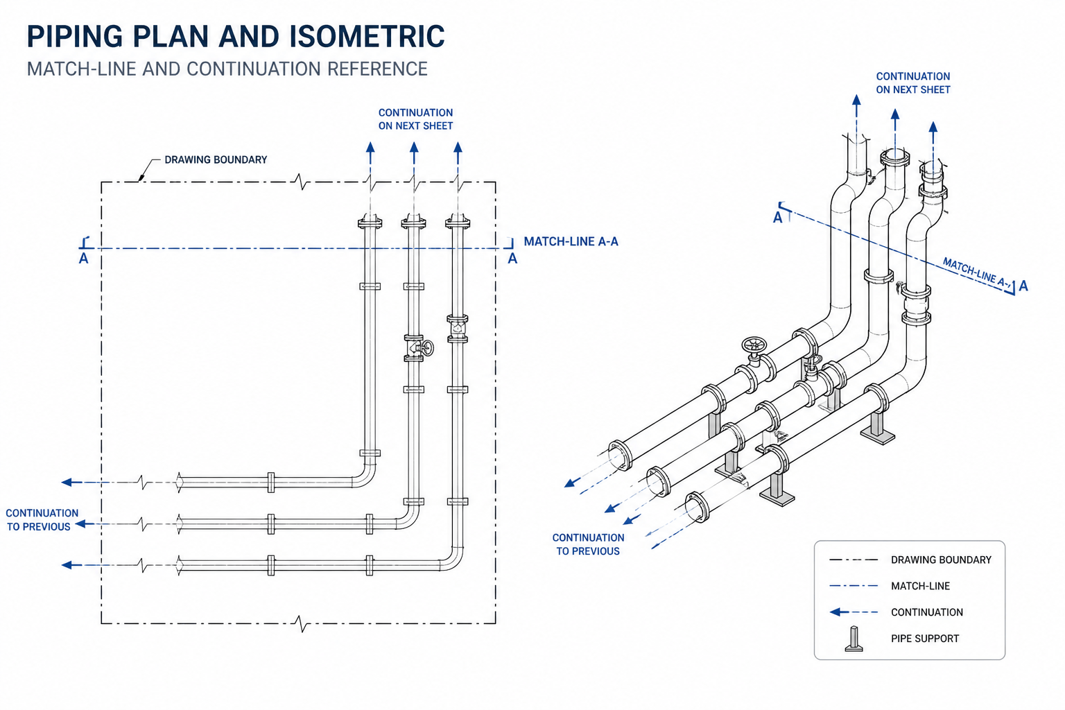
Piping drawing match lines are essential wherever a route crosses a sheet, view, model, or fabrication-document boundary. They connect separate pieces of documentation without suggesting that the pipe physically ends. Clear continuation references help designers, detailers, fabricators, inspectors, and construction teams follow the same piping route across related documents.
This guide explains how to distinguish documentation boundaries from real pipe terminations, what information belongs at a continuation, and how to review match-line references in plans, elevations, sections, and isometric drawings. Use the project drafting standard and drawing legend whenever they define a required symbol or notation.
Large piping systems rarely fit on one plan, section, or isometric sheet. Designers divide the work across drawing areas, model views, or spool documents. When a pipe leaves one view and appears on another, the transition must be unambiguous. That is the purpose of a match line or continuation reference.
A well-detailed match line does more than show where a line disappears. It helps the reader find the continuation, confirms that the two views represent the same physical connection, and preserves important information such as line number, flow direction, elevation, coordinates, and component identity. A weak continuation symbol can create apparent gaps, duplicate equipment connections, or uncertainty during fabrication and construction.
What a piping drawing match line means
A match line identifies the boundary or reference location where a piping route continues into another view or document. The continuation may be on an adjacent plan, another elevation, a different isometric, a spool drawing, or a separate drawing area with its own coordinate system.
The match line is not normally a physical pipe feature. It is a documentation device. It tells the reader that the visible route does not terminate at the sheet boundary or crop region. The pipe continues elsewhere and must be located using the associated reference.
Depending on the project drafting system, the reference may be called a match line, continuation symbol, break reference, off-page connector, or drawing-to-drawing connection. These terms are related but may have different graphical conventions. Always follow the project CAD standard and drawing legend when one is provided.
Match lines versus physical pipe breaks
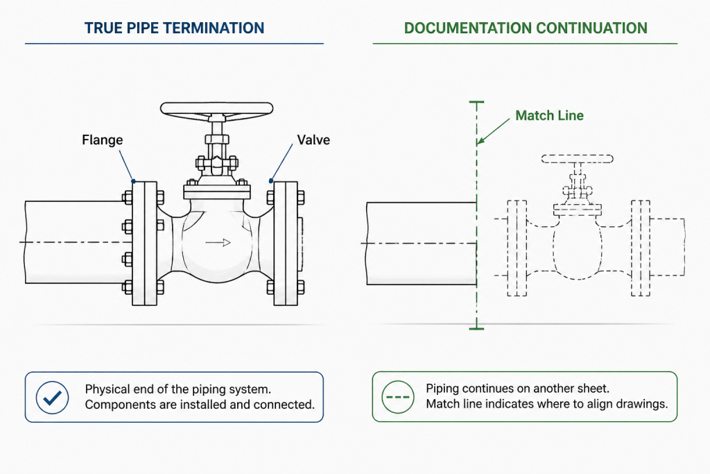
One of the most important drafting decisions is distinguishing a documentation break from a real piping break.
| Situation | What the drawing should communicate |
|---|---|
| Pipe continues outside the view | Use a continuation or match-line reference. Do not imply an open end. |
| Pipe ends at a flange, valve, cap, or equipment nozzle | Show the actual component and connection condition. |
| Pipe is intentionally divided between fabrication documents | Use the project’s spool, sheet, or fabrication break convention and identify both sides clearly. |
| View is shortened only to save space | Use a recognized drafting break, while preserving line identity and continuity information. |
A simple graphical break without a reference can be mistaken for a pipe end, especially in crowded plan views. Conversely, a continuation marker at a real connection can hide an important design condition. The symbol must match the physical meaning.
Information to include at a continuation
The amount of information depends on the drawing type and project requirements, but a useful continuation reference normally answers three questions:
- What continues? Identify the line, branch, or route using the applicable line number, service identifier, or other project tag.
- Where does it continue? Provide the destination drawing, view, area, sheet, model zone, or coordinate reference.
- How should it align? Preserve the relevant orientation, flow direction, elevation, and connection point information.
For an isometric, the continuation may need an explicit direction or coordinate note because the next drawing can use a different viewing orientation. For a plan view, the destination may be obvious from the drawing grid or adjacent sheet index, but the reference should still be readable without relying on visual guesswork.
How to place a match line in CAD
1. Identify the actual boundary
Place the match line where the documented view ends, not where the pipe happens to be easiest to label. In a plan, this may be the sheet edge, a crop boundary, a design area limit, or a deliberately selected coordination boundary. In an isometric, it may be the point where the route transfers to another isometric or spool document.
If the continuation is caused by a model crop or viewport, verify that the crop does not conceal a fitting, support, weld, branch, or change in specification. The match line should represent a controlled documentation boundary rather than an accidental clipping point.
2. Anchor the reference to the pipe centerline
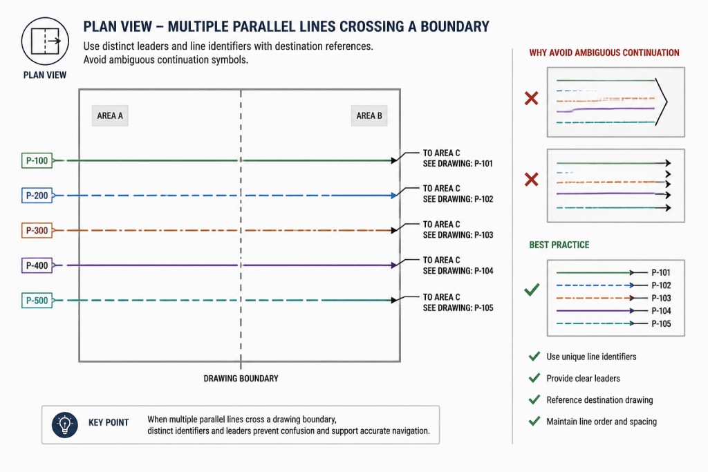
Attach the continuation graphics to the correct pipe segment or branch. Avoid placing a free-floating symbol near several parallel lines. If more than one line crosses the same boundary, each continuation should be distinguishable by location, leader, tag, or other approved drafting method.
For sloping or vertically offset piping, the reference must remain associated with the correct segment even when the linework is compressed. A symbol that appears to touch the wrong pipe can create a connectivity error during review.
3. Add the destination reference
Use a consistent format for the destination. Useful references may include a drawing number, view identifier, continuation label, area designation, or sheet location. The exact format should come from the project’s document-control and CAD conventions.
Do not rely on color alone. Printed drawings, grayscale exports, and field copies may remove color distinctions. Text and geometry should carry the meaning independently.
4. Preserve line and flow identity
Where practical, repeat the line identifier at the continuation. If flow direction matters to interpretation, show or preserve the direction convention used on the drawing. A continuation should not force the reader to infer whether two similarly sized lines belong to the same service.
When the route changes line size, material class, insulation condition, or piping specification near the boundary, locate the change clearly. A match line is not a substitute for a specification break, component tag, or other required annotation.
Continuation symbols on plans, elevations, and isometrics
Plan views
Plan-view continuations should make the horizontal route easy to follow. Check that the reference does not overlap grid bubbles, dimensions, equipment labels, or nearby parallel piping. If a line continues to another plan area, retain enough orientation information for the reader to understand the route between views.
Elevations and sections
In an elevation or section, a pipe can disappear because it crosses behind equipment, passes through a wall, or leaves the section plane. These conditions should not all receive the same symbol. Use a penetration or hidden-line convention when the pipe remains within the same view, and use a continuation reference only when the documented route proceeds beyond the view or drawing boundary.
Isometric drawings
Isometric continuations require particular care because the next document may rotate the route or begin at a different logical point. Confirm the endpoint, branch identity, and destination reference against the model or coordinated source data. Do not use a continuation to conceal an unresolved connection between isometrics.
Common CAD errors and how to prevent them
- Unlabeled pipe ends: A cropped line looks like an open end. Add a clear continuation reference or show the real termination.
- Duplicate continuation labels: Reused labels can send the reader to the wrong view. Use a controlled naming or numbering method.
- Disconnected annotation blocks: Exploded symbols or poorly attached leaders can move during revisions. Anchor the graphics to stable geometry or use controlled CAD blocks.
- Wrong destination after sheet changes: Renamed or split drawings can leave stale references. Include continuation checks in revision control.
- Ambiguous parallel lines: Several pipes may cross the same match boundary. Offset labels and use leaders or unique identifiers.
- Hidden physical components: A crop may remove a valve, flange, branch, or weld near the boundary. Review the model and source view before issuing the drawing.
A practical review checklist
Before issuing a drawing, review every continuation in both directions: from the source view to the destination and from the destination back to the source.
- Does every apparent pipe end have a clear physical or documentation meaning?
- Can the reader identify the continuation without relying on color?
- Does each reference point to the correct drawing, view, or model area?
- Are parallel lines, branches, and nearby components distinguishable?
- Do line numbers, flow indicators, and elevations remain consistent across the boundary?
- Are real flanges, valves, welds, penetrations, and specification changes shown rather than hidden?
- Do revised sheets preserve the same connection logic after cropping, renaming, or re-layout?
Why clear continuation references matter
Match lines are small drawing elements with a large coordination role. They connect separate views into one understandable piping record, support model and drawing reviews, and reduce the risk of treating a documentation boundary as a physical termination. The best practice is simple: show the true condition, identify the continuation precisely, and make the reference remain reliable after the drawing is printed, revised, or read without the CAD model.
How to review a piping match line efficiently
A reliable review starts at the apparent pipe end and follows the reference in both directions. Confirm that the destination exists, that the referenced route is identifiable, and that the connection logic remains consistent between views. This approach is especially useful after drawing revisions, viewport changes, sheet splits, or model coordination updates.
Check the boundary and the meaning
First determine why the pipe is no longer shown. It may continue beyond the documented area, pass into another view, transfer to a spool document, or terminate at a real component. The graphical treatment should communicate that distinction without requiring the reader to inspect the three-dimensional model.
Check the reference as a document-control item
A continuation reference is also a document-control connection. The destination should remain valid after drawings are renamed, reorganized, revised, or reissued. When a sheet or view changes, review both the outgoing and incoming references so that neither side retains obsolete information.
Check the reference in printed output
Review the match line in the format used by the people who will read the drawing. Text, leaders, and geometry should remain legible in grayscale and should not depend on color, screen layers, or hidden CAD information. Crowded labels should be repositioned without weakening their association with the correct pipe.
Relationship to other piping drawing information
Match lines work together with line identifiers, flow indicators, equipment tags, grid references, elevations, branch details, and connection symbols. They do not replace those items. If a route changes specification, direction, elevation, or connection condition near the boundary, the relevant change should be documented separately and kept visually distinct from the continuation marker.
Good coordination also requires consistency between related plan, elevation, section, isometric, and spool views. A continuation that appears clear in one view can still be misleading if the destination view uses a different orientation or omits the corresponding connection information.
Frequently asked questions
Is a match line the same as a pipe break?
No. A match line normally identifies a documentation boundary where the route continues elsewhere. A physical pipe break represents an actual termination, fabrication division, connection, or other condition defined by the project.
Where should a piping continuation symbol be placed?
Place it at the controlled boundary of the documented view and associate it with the correct pipe centerline, branch, or route. Avoid free-floating graphics that could be interpreted as belonging to a nearby parallel line.
What should a continuation reference identify?
It should identify what continues and where the reader can find it. Depending on the project system, that may include a line identifier, destination drawing, view, area, sheet location, or other approved reference. Orientation and flow information may also be needed.
Can a crop boundary hide a valve or fitting?
Yes. A model crop or viewport boundary can conceal a component near the edge of a view. Review the source model and related drawing before issuing the document so that a real valve, flange, branch, weld, support, or specification change is not mistaken for a simple continuation.
How should match lines be checked after a drawing revision?
Check every continuation from the source view to the destination and back again. Confirm that labels, destinations, leaders, line identity, orientation, and related connection information still agree after re-layout, renaming, cropping, or sheet changes.