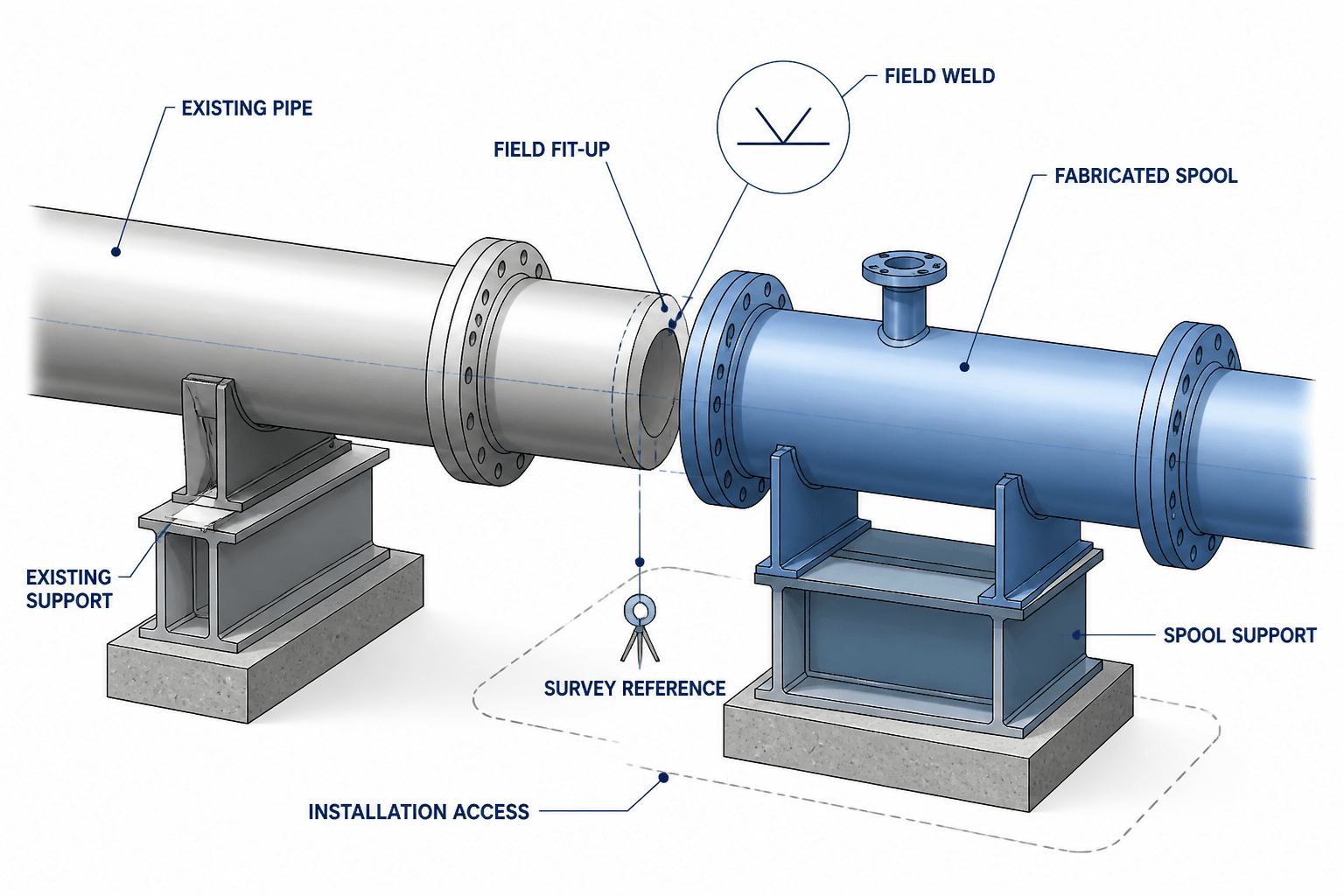
Field fit-up allowances are a coordination tool for managing known installation uncertainty in fabricated piping. They connect the digital model with conditions that may only be confirmed after equipment, structures, or existing pipework are installed and surveyed.
For designers, detailers, fabricators, and construction teams, the important question is not simply whether an allowance exists. The key question is whether its location, limits, ownership, documentation, and closeout method are clear to everyone using the piping deliverables.
This guide explains how to distinguish a controlled fit-up provision from an unexplained CAD gap, how to show the condition in spool and project documentation, and how to preserve accurate as-built information after installation.
Piping field fit-up allowances are deliberate provisions that help a fabricated piping system connect successfully to existing equipment, structures, or adjacent spool pieces during installation. They are not a substitute for accurate design, and they should never be added casually to make an uncertain model appear constructible. In a controlled CAD workflow, a fit-up allowance is a documented coordination decision with a clear location, purpose, owner, and verification method.
This distinction matters because piping drawings often combine precise fabrication information with conditions that cannot be fully confirmed until construction. Existing tie-in points may have survey uncertainty, equipment may be installed slightly differently than shown in a reference model, and field routing may need to accommodate actual steel, insulation, or support conditions. A well-documented allowance manages that uncertainty. An unexplained gap or adjustable-looking dimension creates it.
What a field fit-up allowance means
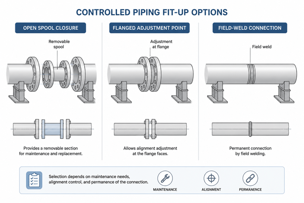
A field fit-up allowance is a planned feature that permits limited adjustment during installation. Depending on the project, it may take the form of a deliberately unfinished closure piece, a field-weld location, a removable spool, a flanged connection, or a defined cut-to-fit segment. The appropriate solution depends on the piping class, fabrication strategy, inspection requirements, access, and the responsible engineering and construction teams.
The allowance must be distinguished from ordinary drafting tolerance. A tolerance describes the acceptable variation in manufacturing or installation. A fit-up allowance is a physical or procedural provision that allows a connection to be completed after actual conditions are verified. Treating one as the other can lead to incorrect spool dimensions, misleading bills of material, and unapproved field changes.
Where fit-up allowances are commonly needed
- Existing-to-new tie-ins: The exact position of an existing pipe, nozzle, valve, or buried connection may require field verification.
- Equipment connections: Equipment models and vendor drawings may not reflect final installed orientation or as-built position.
- Long or complex runs: Accumulated fabrication and erection variation can become significant across a route with many components and welds.
- Interfaces between fabrication areas: Separate shops or work packages may need a controlled closure point between their deliverables.
- Construction-sensitive locations: Pipe rack interfaces, congested modules, and inaccessible weld locations may require a planned installation sequence.
- Survey-dependent work: A connection may remain open until survey data confirms the actual location of a structure or connection point.
Not every uncertain connection needs a fit-up allowance. The first choice should normally be to improve the source information, coordinate the model, or complete a field survey. An allowance is most useful when residual uncertainty is understood and can be controlled.
How to represent the allowance in a CAD model
Show the physical condition honestly
The model should represent what will actually be fabricated and installed. If a spool is intentionally left open, do not model a finished connection that implies the spool is complete. If a field weld is planned, identify the joint in the same manner used for other weld and spool records. If a flange is the planned adjustment point, show the flange, gasket interface, bolt-up direction, and access conditions.
Generic gaps are especially risky. A visible gap without a note can be interpreted as a modeling error, missing component, or incorrect dimension. Use a clear symbol, joint identifier, or annotation that connects the graphical condition to the fabrication and construction documentation.
Define the boundaries
Every allowance should have recognizable boundaries. Identify the upstream and downstream components, spool numbers if applicable, weld or joint identifiers, and the responsible work package. The boundary should also be clear in plan, elevation, section, and isometric views where the connection may be inspected.
For a connection near a nozzle or existing line, the drawing should make clear whether the allowance is part of the new spool, the existing system, or a separate field-installed piece. Ownership is important because it affects material procurement, inspection, weld records, and installation responsibility.
Use dimensions that support the construction decision
Dimensions should explain how the fit-up will be controlled rather than merely showing an attractive nominal geometry. Depending on the project workflow, useful information may include a reference dimension to a known datum, an approximate location identified as such, a cut-to-fit instruction, a survey requirement, or a note directing the installer to verify the field condition before fabrication.
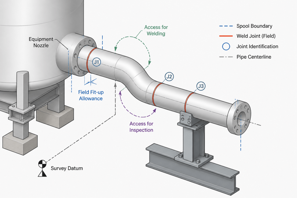
A dimension should not be presented as exact if the value is intentionally subject to field adjustment. Likewise, avoid placing a fabricated spool dimension across an unfinished connection unless the drawing clearly explains how that dimension is to be used. The fabrication dimension, erection reference, and final field measurement may be different types of information and should not be mixed.
Fit-up allowances and spool drawings
When an allowance affects a spool, the spool drawing and the model must agree about what is included. A spool drawing should identify whether the open end is temporary, whether a closure piece is supplied separately, and whether the final connection is welded or bolted in the field. The bill of materials should not quietly include components that are not part of that spool, and it should not omit items needed to complete the connection.
Before issuing a spool, check the following relationships:
- The open or adjustable end is visible and labeled.
- The end preparation and connection type match the intended field operation.
- The spool length does not imply a final dimension that cannot yet be verified.
- Material, inspection, and heat-treatment requirements are assigned to the correct work scope.
- The field joint is not hidden behind a support, platform, insulation break, or inaccessible structure.
- The isometric, plan, model, weld map, and material list use the same joint identity.
Survey control and as-built information
A fit-up allowance is only useful when the project defines how it will be closed. The construction plan may require a survey, a field measurement record, a redline, a controlled sketch, or an approved field change. CAD documentation should identify the information needed before the final piece is cut or the connection is welded.
Use stable project datums for references wherever possible. A local dimension from an uncertain component may become unusable if that component moves during installation. A coordinate, centerline, equipment face, structural grid, or other verified reference may provide better control, provided it is consistent with the project’s drawing conventions.
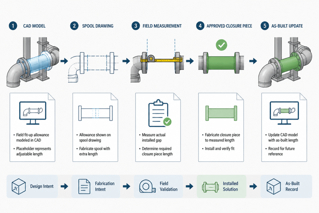
As-built information should return to the design record when the final condition differs from the issued model. This is not just an administrative step. Future maintenance, isolation planning, replacement work, and tie-in design may depend on the final location of the connection.
Common mistakes to avoid
| Mistake | Why it causes trouble | Better practice |
|---|---|---|
| Leaving an unexplained gap in the model | Reviewers cannot tell whether it is intentional or an error. | Label the condition and connect it to a defined field joint or construction note. |
| Using a nominal dimension as a cut dimension | The fabricator may produce a piece that cannot match the installed condition. | Separate design references from dimensions that control fabrication. |
| Placing the field joint where access is poor | The allowance exists geometrically but cannot be installed or inspected efficiently. | Review welding, bolting, lifting, testing, and inspection access in the actual layout. |
| Showing a completed connection in one document and an open connection in another | Different teams may fabricate and install incompatible scopes. | Synchronize the model, isometric, spool drawing, weld records, and material list. |
| Failing to close the allowance in the as-built record | Later users rely on outdated geometry. | Capture the verified final condition through the project’s document-control process. |
A practical review sequence
Review field fit-up allowances in the same order that the work will be executed. First, confirm the source of uncertainty and determine whether better information can remove it. Next, select the physical adjustment method and verify that it is compatible with the piping specification and construction plan. Then place the allowance where it can be fabricated, accessed, inspected, tested, and documented.
After modeling, trace the connection through every affected deliverable. Check the line list, piping specification, model, isometric, spool drawing, weld map, bill of materials, support information, and construction notes. Confirm that each document describes the same boundary and responsibility. Finally, define how the allowance will be measured, approved, closed, and recorded after installation.
The goal is not to add flexibility everywhere. It is to place controlled flexibility only where uncertainty remains and to make that flexibility visible to every team that depends on the piping documents. A field fit-up allowance is successful when it prevents an avoidable field modification while preserving a clear, verifiable design record.
Why fit-up allowances require coordinated documentation
A fit-up allowance sits at the boundary between design intent and field verification. That boundary affects more than the pipe model: it can influence spool release, material responsibility, weld identification, inspection planning, access reviews, and the final as-built record.
The most reliable workflow treats the allowance as a traceable interface. A reviewer should be able to identify the uncertain connection in the model, find the corresponding note or joint identifier on the drawing, determine which work package owns the unfinished condition, and understand what information is required before the connection is completed.
Connect the allowance to the project workflow
CAD representation, fabrication documentation, field measurement, installation, inspection, and document control should describe the same physical condition. If one deliverable shows a finished connection while another shows an open end, the issue is not merely graphical. The discrepancy can cause different teams to work from incompatible assumptions.
For that reason, fit-up review is best performed as a document-to-document trace rather than as an isolated model check. Follow the connection through the model, isometric, spool drawing, weld information, material documentation, construction notes, and as-built process. This approach helps expose unclear boundaries before fabrication or installation begins.
Use the allowance only for residual uncertainty
A planned allowance should not replace information that can reasonably be obtained through design coordination, vendor confirmation, survey, or field verification. First identify what is uncertain and whether that uncertainty can be removed. If it remains, select an adjustment method that can be controlled, accessed, inspected, and recorded under the project workflow.
This distinction also improves future maintenance. Once the final connection is verified, returning the condition to the design record gives later users a dependable basis for isolation planning, replacement work, and additional tie-ins.
Frequently asked questions
Is a fit-up allowance the same as a drafting tolerance?
No. A tolerance describes acceptable variation in fabrication or installation. A fit-up allowance is a planned physical or procedural provision that permits a connection to be completed after actual conditions are verified.
Should every uncertain connection receive a fit-up allowance?
No. The preferred first step is usually to improve the source information, coordinate the model, or complete a field survey. An allowance is appropriate when residual uncertainty is understood and can be controlled.
How should an unfinished connection appear in a CAD model?
The model should show the condition that will actually be fabricated and installed. Use a clear joint identifier, symbol, or annotation so that an open end or adjustable connection cannot be mistaken for a modeling error or missing component.
What information should define the allowance?
Define the connected components, the joint or spool boundaries, the responsible work package, the adjustment method, and the verification or closeout process. The same identity should be used across affected drawings and records.
Why are stable datums important for fit-up control?
A reference tied to an uncertain component may become unreliable if that component moves during installation. A verified project datum, centerline, equipment face, structural reference, or other accepted reference can provide more dependable control when used consistently.
What happens after the field connection is completed?
The verified final condition should be captured through the project document-control process. If it differs from the issued model, the design record should be updated so future users do not rely on outdated geometry.