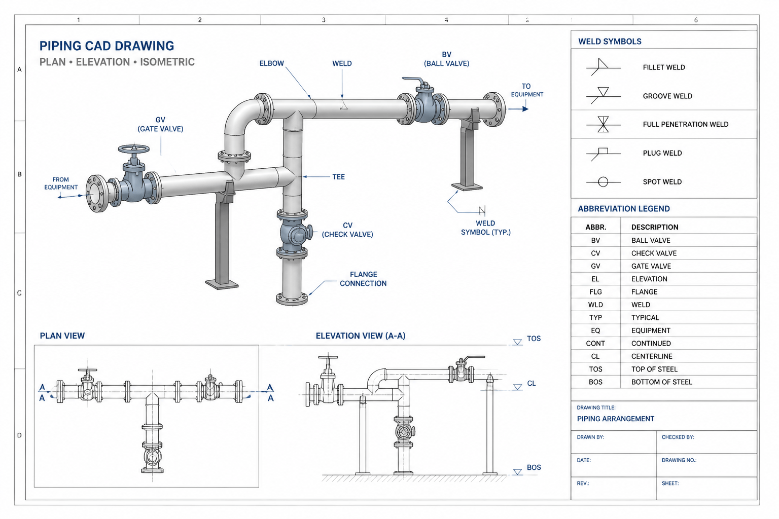
Piping drawing abbreviations compress a large amount of design information into labels, symbols, schedules, and CAD attributes. That efficiency helps keep crowded drawings readable, but it also creates a review risk: a familiar abbreviation can be interpreted incorrectly when its project context is missing.
This guide explains how to read common piping callouts without treating shorthand as a complete specification. Use the drawing legend, line data, material requirements, fabrication notes, and related source documents to confirm what each abbreviation means and which component attribute it controls.
Piping drawings use compact abbreviations to communicate routing, components, materials, fabrication requirements, and inspection information without overcrowding the sheet. A short note such as FLG, BW, FW, or CL EL can affect how a model is interpreted, how a spool is fabricated, or how a connection is reviewed.
The difficulty is that piping abbreviations are not always universal. Some are widely recognized, while others are defined by a project, company, owner, or CAD standards manual. The safest approach is to treat an abbreviation as a controlled piece of design information, not as a guess based only on familiar letters.
Why piping abbreviations require context
A piping note rarely stands alone. Its meaning depends on where it appears and what information surrounds it. The same short form may describe a component, an orientation, a fabrication instruction, or a document reference.
- Location: A note beside a weld symbol may describe fabrication or inspection, while a note in a title block may describe document status.
- Graphic relationship: A callout attached to a valve, flange, or branch has a different role from a note placed near a line number.
- Project legend: The drawing legend or abbreviation list controls project-specific meanings.
- Source document: A P&ID, isometric, plot plan, and spool drawing may use different levels of detail.
- Data field: A CAD property, bill of material column, and drawing annotation may use different labels for the same concept.
Before expanding an unfamiliar abbreviation, check the drawing legend, piping material specification, line list, title block notes, and applicable drafting procedure. If those sources disagree, record the conflict rather than silently choosing an interpretation.
Common piping drawing abbreviation groups
The following groups are useful for initial reading. They are practical examples, not a replacement for the governing project abbreviation list.
| Abbreviation group | Typical examples | What to check |
|---|---|---|
| Component type | ELB, TEE, RED, CAP, FLG, VAL | Confirm the component description, nominal size, end connection, and material designation. |
| Connection type | BW, SW, THD, FL | Check whether the notation describes both ends or only the end being called out. |
| Welding and fabrication | FW, shop weld, field weld, seam or joint notes | Review the weld legend and determine whether the note identifies location, sequence, or inspection. |
| Elevation and orientation | CL EL, BOP, TOP, INV, N, E | Verify the project datum, reference direction, and whether the elevation applies to the pipe centerline or surface. |
| Insulation and tracing | INSUL, HT, ST, tracing notes | Check the insulation class, tracing requirement, removable areas, and support interfaces. |
| Inspection and testing | NDE, PMI, RT, UT, PT, MT | Use the project inspection plan to determine the exact examination or verification requirement. |
| Documentation status | IFR, IFC, AS-BUILT, REV | Confirm the document control procedure and the status meaning used on that project. |
Component callouts: read the whole identification
A component callout may contain more information than its abbreviated type. A valve, for example, can be identified through a tag, nominal size, pressure class or rating designation, material class, end connection, and operator information. A fitting callout may identify the fitting type, size transition, schedule, material, and item number.
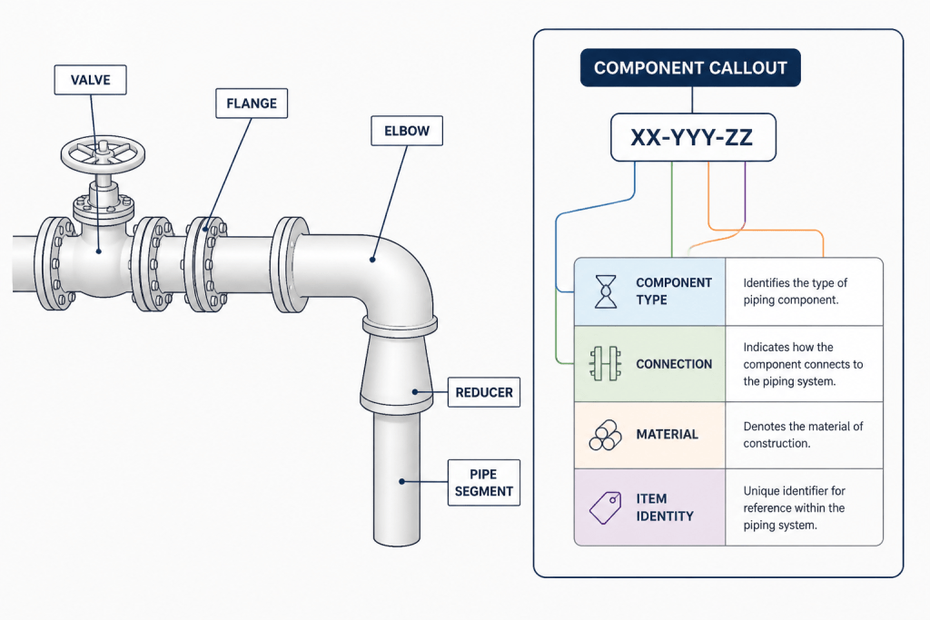
Do not assume that the abbreviated component name defines every required attribute. ELB may identify an elbow, but it does not by itself establish the bend radius, angle, wall thickness, material, or connection type. Those attributes usually come from the line specification, component catalog, bill of material, or detailed item description.
Separate graphic identity from specification identity
The symbol or block in a CAD drawing communicates where an item is located and how it connects geometrically. The specification data determines whether the item belongs in that location. A visually correct block can still contain the wrong end preparation, rating, material, or catalog description.
During review, compare three related records:
- The drawing tag or item number.
- The CAD block or model properties.
- The bill of material or component schedule description.
If one of these differs, resolve the data discrepancy before fabrication or procurement information is issued.
Connection abbreviations and end conditions
Connection abbreviations are especially important because they influence both geometry and fabrication. Common categories include butt-weld, socket-weld, threaded, flanged, and mechanical or proprietary connections. A short form placed at one end of a component may not describe the opposite end.
When reading a connection note, check:
- Which end or face the abbreviation applies to.
- Whether the connection is shown graphically or only described in a schedule.
- Whether the mating component uses a compatible connection type.
- Whether a transition piece, gasket, bolt set, or adapter is required.
- Whether the connection is shop-fabricated, field-installed, or supplied by a vendor.
For flanged joints, the abbreviation alone is not enough to verify the connection. The flange facing, gasket arrangement, bolting information, material class, and orientation still need to be checked against the applicable project data.
Elevation and direction callouts
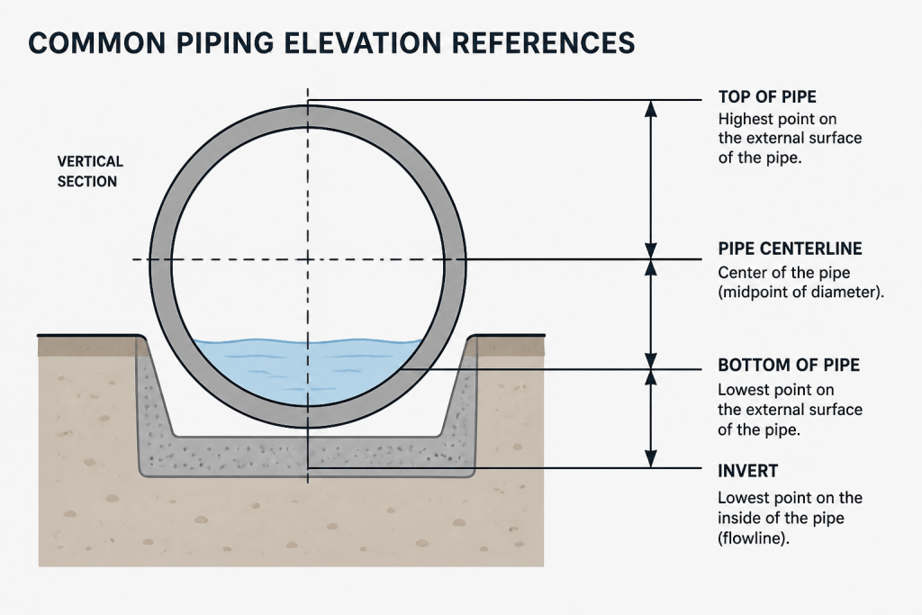
Elevation abbreviations often appear near dimensions, centerlines, equipment nozzles, and support locations. Common terms may refer to the pipe centerline, bottom of pipe, top of pipe, or invert. These references are not interchangeable.
A vertical dimension should be read together with its stated reference. For example, a dimension to the pipe centerline cannot be used directly as a dimension to the bottom of the pipe unless the outside diameter, insulation, lining, or other relevant layer is accounted for. The drawing should make the reference clear through a leader, extension line, symbol, or note.
Direction callouts also need a defined coordinate basis. North arrows, plant coordinates, grid references, and equipment orientation marks should be read from the drawing control information rather than inferred from the sheet layout.
Weld, inspection, and fabrication notes
Abbreviations near weld symbols can describe the weld location, fabrication responsibility, examination method, or documentation requirement. A field-weld mark, for instance, identifies an installation condition, but it may not explain the full welding procedure or inspection extent.
Use the weld legend and fabrication documents to answer questions such as:
- Is the weld intended for the shop or the field?
- Does the mark identify a joint number or only a weld category?
- Is the inspection abbreviation a method, an acceptance record, or a general note?
- Does the weld belong to the piping spool, an equipment nozzle, or a vendor package?
- Must the weld be tracked in a weld map, inspection report, or turnover record?
Avoid expanding an inspection abbreviation into a project requirement unless the inspection plan or governing documentation confirms it. Drawing shorthand is an index to the requirement, not always the requirement itself.
A practical workflow for decoding an unfamiliar callout
- Identify the object. Determine whether the note refers to a pipe, fitting, valve, weld, support, dimension, or document status.
- Read adjacent information. Review the line number, item number, material class, leader, symbol, and nearby notes.
- Check the legend. Use the drawing-specific abbreviation list before relying on general industry familiarity.
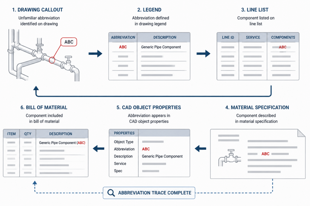
- Trace the source. Compare the callout with the P&ID, line list, material specification, isometric, or equipment data.
- Confirm the CAD data. Check the block attributes, object properties, layer, and bill of material entry.
- Record uncertainty. Mark unresolved meanings as review items instead of converting assumptions into model data.
How to improve abbreviation use in CAD standards
A reliable CAD standard should define abbreviations in one controlled location and apply them consistently across model properties, annotations, schedules, and extracted bills of material. Each abbreviation should have a clear description, permitted context, and owner responsible for maintaining it.
Good practice includes using readable descriptions for critical fabrication information, avoiding overloaded abbreviations, and preserving the full value in object data even when the drawing displays a shortened form. Automated checks can then compare displayed callouts with the underlying component and line data.
When a project uses a nonstandard abbreviation, define it near the first relevant use or in the drawing legend. Clarity is more valuable than saving a few characters, especially when drawings will be reviewed by designers, fabricators, inspectors, operators, and contractors from different organizations.
Final review checklist
- Is the abbreviation defined by the drawing, project, or company legend?
- Does the callout clearly identify the object and the attribute being described?
- Are connection, orientation, elevation, and fabrication meanings separated?
- Do the tag, CAD object, schedule, and source document agree?
- Are project-specific meanings distinguished from broadly recognized terms?
- Have ambiguous notes been assigned for clarification before issue?
Piping abbreviations make drawings efficient, but only when their meaning remains traceable. Treat each callout as part of a connected information system: the graphic shows location and relationship, while specifications, schedules, and controlled project documents define what the item actually is.
Use callouts as linked design data
A piping callout is most reliable when it can be traced through the drawing and its supporting records. The graphic may identify location, connectivity, or orientation, while the line list, material specification, component schedule, and fabrication documentation provide the detail needed for modeling, procurement, and construction review.
When checking a note in a CAD environment, look beyond the visible text. Review the leader attachment, layer, block attributes, object properties, item number, and nearby dimensions or symbols. This helps distinguish a note that identifies an object from one that qualifies its material, connection, fabrication status, inspection path, or document status.
Common interpretation mistakes
- Expanding letters from memory: A familiar abbreviation may have a different meaning in a project legend or company standard.
- Applying an end condition to the entire component: A connection note may apply to one end or face rather than both ends.
- Confusing location with specification: A CAD symbol can show where an item belongs without proving that its catalog data is correct.
- Using an elevation without its reference: Centerline, top, bottom, and invert references must remain connected to the stated datum.
- Treating an inspection shorthand as a complete requirement: The inspection plan and fabrication documents determine the applicable method, extent, and record.
Review habits that improve drawing quality
Teams can reduce ambiguity by maintaining one controlled abbreviation list and using the same terminology in annotations, model properties, schedules, and extracted bills of material. Critical fabrication information should remain available in full within the underlying data even when the sheet uses a shortened display label.
During interdisciplinary review, record unresolved abbreviations as explicit clarification items. This creates a traceable decision instead of allowing an assumption to pass into a model, spool, purchase description, or inspection record. The goal is not to eliminate concise notation, but to ensure that every short form has a dependable path to its full meaning.
Frequently asked questions
Are piping drawing abbreviations universal?
No. Some abbreviations are widely recognized, but project, company, owner, and CAD standards can assign different meanings. The applicable drawing legend and controlled project documentation take precedence.
Does a component abbreviation define the complete item?
No. A short form such as an elbow or valve identifier generally indicates the component category only. Size, material, connection, rating, geometry, operator information, and other attributes must be confirmed from the relevant schedule, specification, catalog, or item description.
How should an unfamiliar callout be checked?
First identify the object and read the adjacent symbols and data. Then check the drawing legend, trace the note to related source documents, compare the CAD properties with the schedule, and record any unresolved interpretation for review.
Can a connection abbreviation describe both ends of a component?
Not necessarily. Check which end or face the note refers to and verify the opposite end separately. The mating component, transition details, gasket or bolting information, and fabrication responsibility may also need review.
What is the difference between a CAD symbol and specification data?
The symbol or block primarily communicates graphic location and geometric relationship. Specification data determines whether the selected item has the required description, material, connection, and other project attributes.
Where should project-specific abbreviations be defined?
Define them in the controlled drawing legend or CAD standard, and clarify them near the first relevant use when necessary. The definition should indicate the permitted context and remain consistent across drawings, model data, schedules, and bills of material.