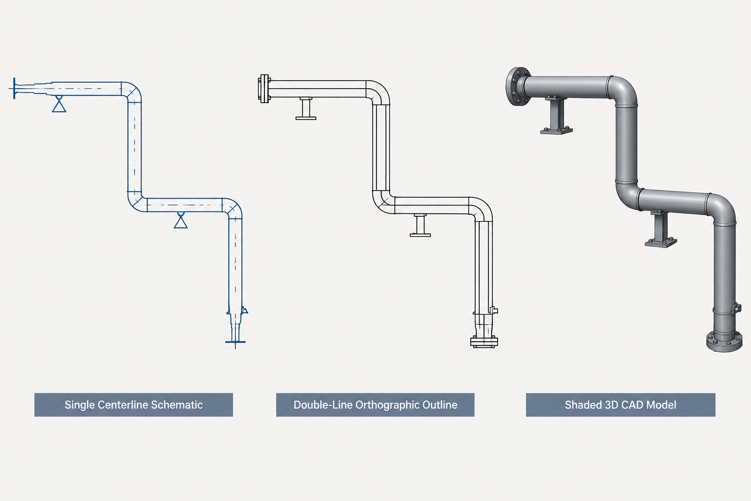
Piping CAD graphics range from schematic centerlines to physical outlines and fully spatial component models. The correct choice depends on what the drawing must communicate, the reliability of the available component data, and the decisions reviewers need to make.
This guide compares single-line, double-line, and 3D piping drawings without treating added detail as automatic improvement. It explains how to match representation to routing, coordination, documentation, and review tasks while avoiding false precision.
A pipe can appear as a simple centerline, a pair of lines showing its outside envelope, or a fully modeled three-dimensional component. Each representation communicates different information. Choosing the wrong one can make a drawing crowded, imply accuracy that does not exist, or hide the space needed for fittings, insulation, and maintenance.
The best piping CAD representation is not necessarily the most detailed. It is the one that clearly supports the drawing’s purpose while remaining consistent with the project data. Reference tables and approved component catalogs should provide actual dimensions; the drawing method determines how those dimensions are communicated.
The three common representation methods
| Representation | What it emphasizes | Common uses | Main limitation |
|---|---|---|---|
| Single-line | Centerline path and connectivity | Schematics, routing studies, diagrams, and small-scale plans | Does not directly show the physical pipe envelope |
| Double-line | Visible pipe width and component outlines | Detailed plans, elevations, sections, and installation details | Can become visually congested |
| 3D model | Spatial volume, orientation, and interfaces | Coordination, visualization, interference review, and drawing extraction | Its apparent precision may exceed the quality of the underlying data |
These methods are not competing drafting styles. A project may use all three, sometimes for the same line. A process diagram may use symbolic single-line graphics, a general arrangement may use centerlines or simplified outlines, and a detailed model may contain catalog-based solids.
Single-line piping: prioritize routing and connectivity
In a single-line drawing, the pipe centerline represents the route. Elbows, tees, reducers, valves, and other components may be shown with symbols or simplified geometry. The line itself does not represent the inside or outside diameter.
This method is effective when the reader needs to understand where the line goes, what it connects to, and how branches relate to the main run. It also works well where the drawing scale is too small for physical outlines to remain legible.
What single-line graphics should communicate
- A continuous and unambiguous flow path
- Branch locations and connection relationships
- Component sequence
- Line identification and specification changes
- Relevant elevations, coordinates, slopes, or directional changes
- Clear continuation at match lines or drawing boundaries
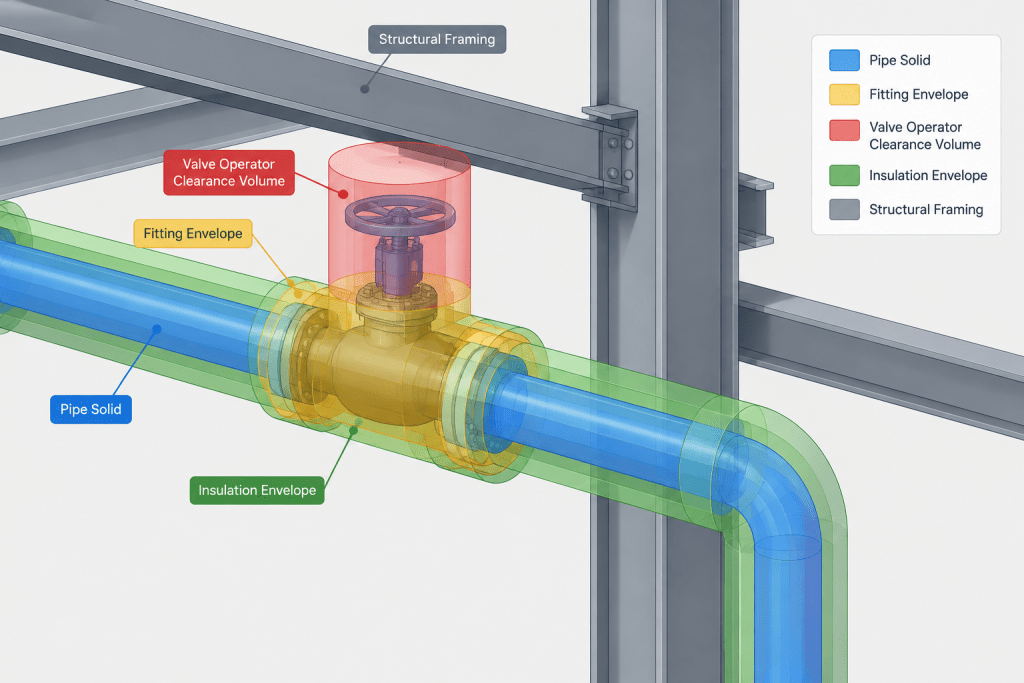
A common mistake is treating a centerline drawing as though it proves clearance. Two centerlines may appear separated while the actual pipe envelopes, flanges, insulation, or valve operators overlap. Clearance decisions must use verified outside dimensions and the applicable surrounding envelopes.
Double-line piping: show the physical envelope
Double-line representation uses visible edges or outlines to suggest the pipe’s outside surface in an orthographic view. Fittings and inline components are usually drawn with recognizable outlines rather than schematic symbols.
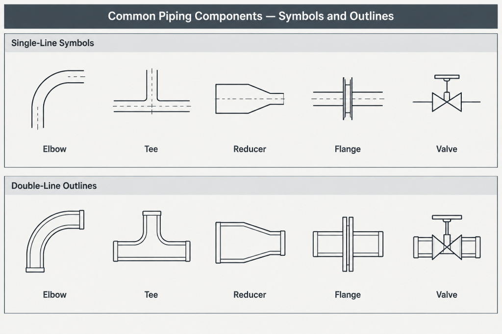
This approach is useful when the physical width of piping affects coordination or construction interpretation. It can clarify relationships at equipment nozzles, penetrations, congested racks, support interfaces, and closely spaced parallel runs.
Double-line drawings require more disciplined drafting than centerline layouts. The visible width must come from the correct outside diameter, not from nominal pipe size interpreted as a measured diameter. Reducer lengths, elbow geometry, flange projections, and valve dimensions should come from authoritative project data or approved manufacturer information.
Where double-line drawings become difficult
At small plotting scales, outlines can merge and fittings can become unreadable. Dense parallel piping may produce a mass of lines that obscures tags and dimensions. In those conditions, a simplified centerline view, enlarged detail, or sectional view may communicate more effectively than forcing every physical edge into the same view.
Hidden lines should also be used selectively. Showing every concealed edge can create clutter without improving interpretation. Use view direction, sections, break lines, and notes to reveal important geometry instead of relying on an excessive hidden-line network.
3D piping: coordinate volume and orientation
A 3D piping model can represent the pipe body, fittings, flanges, valves, supports, and equipment interfaces as spatial objects. It is particularly useful for checking routing relationships and generating coordinated plans, elevations, sections, and isometric views.
However, a solid that looks realistic is not automatically correct. Its reliability depends on the component definition, insertion point, end-connection geometry, orientation, and assigned metadata. A generic valve solid may be adequate for an early layout but inappropriate for a final access or interface review if its body and operator envelope are placeholders.
Classify model content by data quality
- Catalog-based: Geometry is built from controlled dimensional data appropriate to the project specification.
- Vendor-based: Geometry reflects reviewed equipment or component information supplied for the project.
- Generic: Geometry represents a component type but not an approved product.
- Reserved envelope: A simplified volume protects space for an item whose final geometry is unavailable.
This classification should be visible in model properties, naming conventions, review notes, or another controlled project method. Reviewers should not have to guess whether a detailed-looking object is verified.
How representation changes by project stage
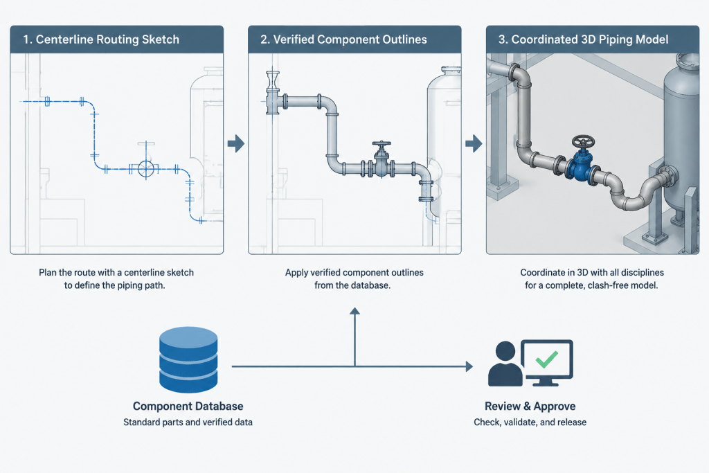
Early routing work often benefits from centerlines and simple reserved volumes. These are quick to revise and make alternatives easier to compare. As interfaces become fixed, selected areas can transition to dimensional outlines or catalog-based components.
A practical progression is:
- Establish connectivity and major routing with centerlines.
- Assign line size, specification, and other required properties.
- Apply verified outside dimensions to evaluate physical envelopes.
- Replace generic fittings and valves where detailed geometry matters.
- Add insulation, operator, removal, and access envelopes as separate coordination objects.
- Extract drawing views using a display style appropriate to their scale and purpose.
- Check extracted graphics against the model and source data.
Not every component needs to progress to maximum geometric detail. Small features that do not affect coordination may remain symbolic or simplified, provided the documentation makes that limitation clear.
Keep nominal size separate from drawn geometry
Nominal pipe size is an identification system, not a direct instruction to draw the pipe at that measured width. For double-line and 3D work, use the verified outside diameter from the site’s authoritative dimension tables or approved project catalog. Wall thickness and schedule influence internal geometry and material definition, but they do not normally change the standard outside envelope for a given pipe size system.
This distinction matters when a model contains both graphical geometry and data fields. A component can display the correct line size while using the wrong outside diameter, or it can look correct while carrying the wrong schedule or material property. Geometry and metadata require separate checks.
Represent components according to drawing purpose
Elbows and bends
A single-line elbow may be an arc or a schematic turn. A double-line elbow should reflect the applicable center-to-end geometry and outside envelope. In 3D, verify that the fitting definition matches the intended component type rather than assuming every curved route uses the same radius.
Reducers
Single-line reducers are often indicated by a symbol or centerline transition. Detailed views should show the actual end sizes, length, and concentric or eccentric form from verified data. For eccentric reducers, the orientation of the offset is as important as the outline.
Flanges
At a small scale, a flange may be represented by short transverse lines or a simplified symbol. Detailed coordination may require the outside envelope, thickness, facing interface, and bolt-clearance region. Dimensions should come from the applicable reference data rather than from the visual proportions of a symbol.
Valves and specialty items
A schematic valve symbol communicates function, while a detailed model communicates body size, end connections, operator orientation, and spatial envelope. Do not infer installation clearance from a schematic symbol. If approved product geometry is unavailable, show a clearly identified reserved envelope.
Dimension from controlled references
Dimensions should describe the design intent, not merely report whatever a drafter can snap to. Centerline routing dimensions typically locate intersections, fitting centers, equipment nozzles, and established datums. Detail dimensions may also locate faces, ends, supports, and interface points.
Avoid dimensioning to incidental silhouette points on curved solids or to tessellated display edges. Such points may change when the model is regenerated or displayed at a different resolution. Use stable component origins, connection points, centerlines, and defined faces.
If simplified graphics are not to scale, state that clearly and avoid adding dimensions that imply a measured relationship. Conversely, a scale drawing should still rely on written dimensions and controlled data for fabrication or installation interpretation.
Managing mixed representation on one drawing
Mixed representation is acceptable when it is deliberate. A plan may show most piping as centerlines while using double-line detail around a congested equipment connection. A 3D-derived view may include symbolic annotations for valves or instruments.
To prevent confusion:
- Use a consistent convention within each view.
- Identify enlarged areas and their relationship to the parent view.
- Do not let symbolic graphics resemble dimensionally accurate outlines.
- Control layers or display states so duplicate centerlines and outlines do not compete.
- Explain unusual simplifications in the legend or drawing notes.
- Confirm that tags and callouts remain linked to the correct modeled objects.
CAD review checklist
- Does the representation match the drawing’s intended use and plot scale?
- Are nominal sizes separated from actual modeled outside dimensions?
- Were fitting and flange dimensions taken from controlled reference data?
- Are generic and verified model components distinguishable?
- Do centerline connections remain continuous through fittings and branches?
- Are eccentric components and valve operators oriented correctly?
- Have insulation and access envelopes been considered where relevant?
- Are hidden lines limited to information that improves understanding?
- Do dimensions attach to stable connection points, faces, or datums?
- Can the reader tell which graphics are schematic, simplified, or physically modeled?
Choose clarity before detail
A successful piping drawing does not show the maximum amount of geometry. It shows the right geometry for the decision being made. Single-line drawings explain routes and relationships efficiently. Double-line drawings clarify physical width and local interfaces. Three-dimensional models support spatial coordination and drawing extraction when their source data is controlled.
Whichever method is used, keep graphical detail aligned with data quality. Use authoritative dimension tables for pipe and component geometry, label placeholders honestly, and avoid allowing a realistic appearance to imply unverified precision.
A practical method for selecting the representation
Begin by identifying the question the drawing must answer. If the task concerns connectivity, component sequence, or general routing, a centerline view may communicate the design most efficiently. If the task concerns physical width, local interfaces, or installation interpretation, outlines may be necessary. If orientation, surrounding objects, or access space must be coordinated, a spatial model can provide the required context.
Next, compare the requested detail with the quality of the source data. A detailed-looking object should not be treated as verified merely because it has realistic geometry. Where approved dimensions are unavailable, use a clearly identified generic object or reserved envelope rather than implying product-specific accuracy.
Define acceptance criteria before drafting
- Purpose: State whether the view supports routing, coordination, construction interpretation, review, or another defined task.
- Data status: Distinguish controlled component geometry from generic or provisional content.
- Display convention: Establish whether each view uses centerlines, outlines, modeled objects, or an intentional combination.
- Reference basis: Confirm that physical dimensions come from authoritative tables, approved catalogs, or reviewed vendor information.
- Review scope: Identify whether the review covers connectivity, physical envelopes, interfaces, access, or model metadata.
Preserve meaning when views are exchanged
Representation can change when a model is exported, referenced into another CAD environment, or converted into a plotted drawing. Centerlines may disappear, hidden edges may become prominent, and symbolic components may be mistaken for physical geometry. Display settings therefore need the same level of review as object placement.
A reliable handoff should preserve line identification, connection points, component orientation, and the distinction between verified and provisional geometry. When the receiving format cannot retain model properties, communicate those limitations through controlled notes, legends, layers, or naming conventions.
Use detail as a controlled communication tool
Geometric detail is valuable only when it helps the reader make the intended decision. Excess detail can conceal routes, compete with dimensions, and make revision control harder. Too little detail can hide physical conflicts or leave an interface open to interpretation.
The strongest workflow separates the design data from its display style. Pipe size, specification, component identity, and dimensional references remain controlled information, while each drawing view presents only the geometry needed for its purpose.
Frequently asked questions
Is a single-line piping drawing drawn to the pipe outside diameter?
No. The line represents the routing centerline rather than the pipe surface. Physical envelope checks require verified outside dimensions and any additional surrounding envelopes relevant to the review.
Does double-line representation show the pipe wall thickness?
Not necessarily. In an orthographic piping view, the paired outlines commonly communicate the visible outside envelope. Internal geometry should be shown only when the drawing purpose requires it and the supporting data is controlled.
Can a realistic 3D component be assumed to match the selected product?
No. Appearance alone does not establish dimensional authority. Review the component source, data status, connection geometry, orientation, and metadata before relying on it for an interface or clearance decision.
Can single-line and double-line graphics appear on the same drawing?
Yes, when the change is intentional and clearly communicated. Separate views, enlarged details, display controls, and notes can prevent readers from confusing symbolic graphics with dimensionally based outlines.
When should a generic model be replaced?
Replace or supplement generic geometry when the component’s actual body, connection, operator, removal, or access envelope affects the decision under review. Until verified information is available, identify the object as provisional.
Which representation is best for fabrication or installation dimensions?
No representation is sufficient by itself. Written dimensions should reference stable datums, connection points, centers, or defined faces and should be supported by controlled project data. The selected graphics should make those dimensions clear rather than serve as a substitute for them.