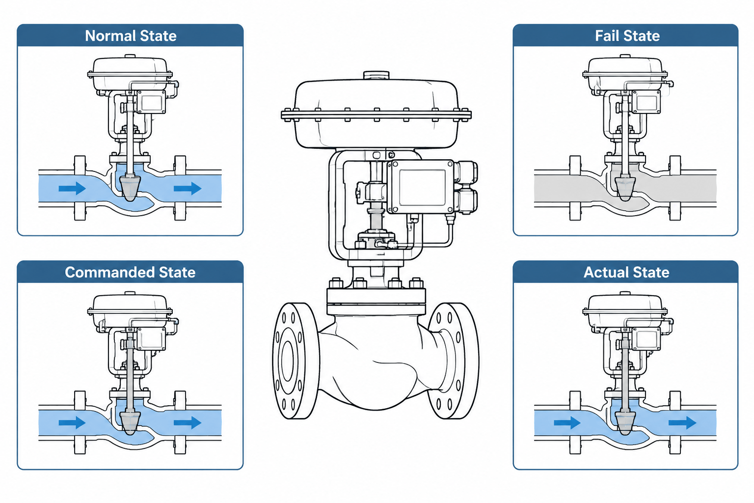
Valve position terminology describes several different aspects of valve behavior. Normal position defines an expected operating line-up, fail position describes the intended response to a specified loss condition, commanded position records what the control system requests, and actual position reports the physical state.
This distinction is essential when reviewing P&IDs, valve lists, control information, CAD properties, and commissioning records. The following reference explains how to keep these states separate, identify ambiguous notes, and transfer approved valve information without inferring behavior from a symbol or model graphic.
Valve position terminology can look simple until several disciplines use the same words differently. A process engineer may describe a valve as normally open, an instrument engineer may specify fail closed, and an operator may report that the valve is currently at a partially open position. All three statements can be correct because they describe different conditions.
For piping designers and CAD drafters, the main challenge is not deciding how the valve should operate. That responsibility belongs to the appropriate process, controls, safety, mechanical, and operations teams. The drafting task is to preserve the approved intent without collapsing several distinct valve states into one ambiguous note or symbol.
The Four Valve States That Should Not Be Confused
A valve can have multiple state descriptions attached to it. Each answers a different question:
| State description | Question it answers | Typical use |
|---|---|---|
| Normal position | Where is the valve expected to be during the defined normal operating condition? | P&IDs, operating procedures, valve lists, and line-up drawings |
| Fail position | What position is intended after loss of a specified utility or signal? | Control-valve data, shutdown philosophy, cause-and-effect information, and P&IDs |
| Commanded position | What position is the control or shutdown system requesting? | Control logic, automation displays, testing, and commissioning |
| Actual position | What position is the valve physically in now? | Position feedback, field inspection, commissioning records, and operations |
A model or drawing that records only “open” or “closed” may therefore be incomplete. The word could refer to normal operation, a failure response, a system command, or the observed field condition.
Normal Position Is an Operating Definition
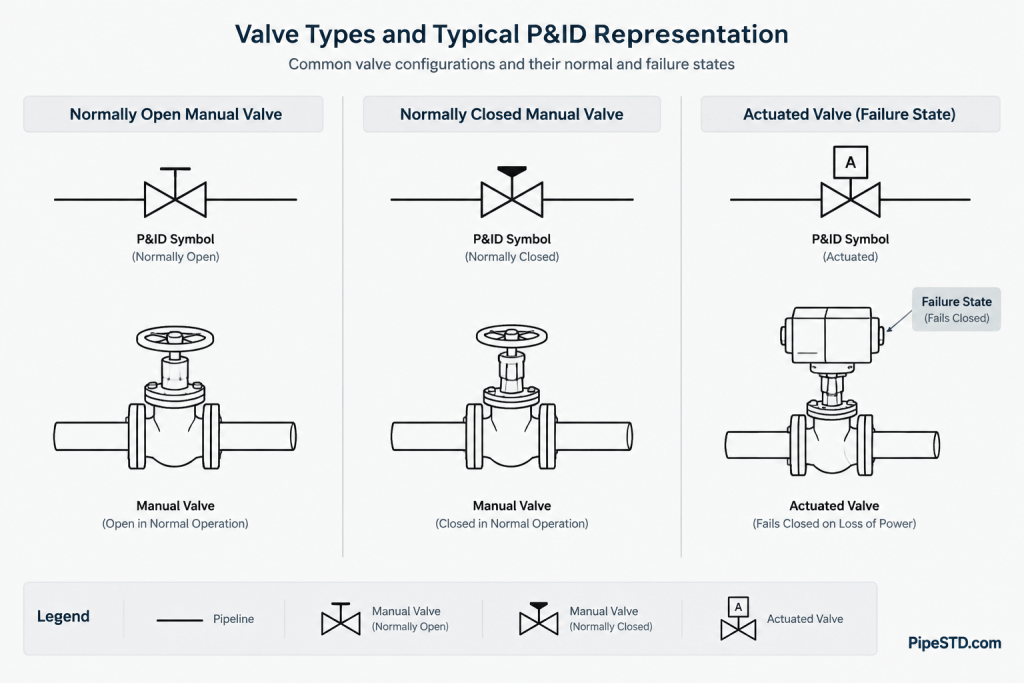
Normally open and normally closed generally describe an expected operating line-up under a defined condition. They do not automatically describe what happens during loss of power, air, hydraulic pressure, or a control signal.
For a manual isolation valve, the normal position may be open because flow normally passes through the line. A bypass valve around equipment may normally be closed but opened during maintenance or a special operating mode. A drain valve may be closed during operation and used only when the system is isolated.
The phrase “normal operation” must itself be understood. Startup, shutdown, regeneration, cleaning, testing, standby, and emergency operation can require different line-ups. If the project has several operating modes, a single normal-position label may not communicate enough information. The source document or project legend should define the intended basis.
Locked, Car-Sealed, and Administratively Controlled Positions
Some valves have position controls such as locks, seals, or operating restrictions. These controls are not merely alternate ways to say normally open or normally closed. A normal position describes operating intent, while a lock or seal describes how the position is controlled or monitored.
Do not add such designations based on visual assumptions or common practice. They should come from approved project information and remain consistent across the P&ID, valve list, operating documentation, and field identification system.
Fail Position Requires a Defined Failure
Fail open, fail closed, and fail in place are commonly associated with actuated valves. These terms describe the intended response to a stated failure condition. They should not be treated as universal behavior under every possible malfunction.
- Fail open: the valve is intended to move toward the open position when the specified actuating resource or signal is lost.
- Fail closed: the valve is intended to move toward the closed position under the specified failure condition.
- Fail in place: the valve is intended to remain near its last position, subject to the actual actuator and system behavior.
- Fail to a defined intermediate position: some applications require a position other than fully open or fully closed.
The failure basis matters. Loss of electrical power, loss of instrument air, loss of hydraulic pressure, loss of control signal, and mechanical actuator failure are not necessarily equivalent. A stored-energy device, accumulator, solenoid arrangement, or control strategy can produce different responses for different events.
A drafter should therefore avoid converting a generic note such as “air failure” into a broader statement about all failures. When the source documents disagree or the failure basis is missing, the correct action is to raise a technical query rather than infer the answer from actuator appearance.
Actuator Action Is Not the Same as Valve Fail Position
Terms describing actuator action, spring action, or signal response are related to fail position but are not interchangeable with it. The final valve behavior depends on the complete assembly: actuator, valve mechanism, linkage, accessories, energy source, and control arrangement.
For example, increasing a control signal may drive an actuator in one direction, but whether that opens or closes the process path depends on the valve assembly. Similarly, a spring direction alone does not communicate every failure response if stored energy or auxiliary controls are present.
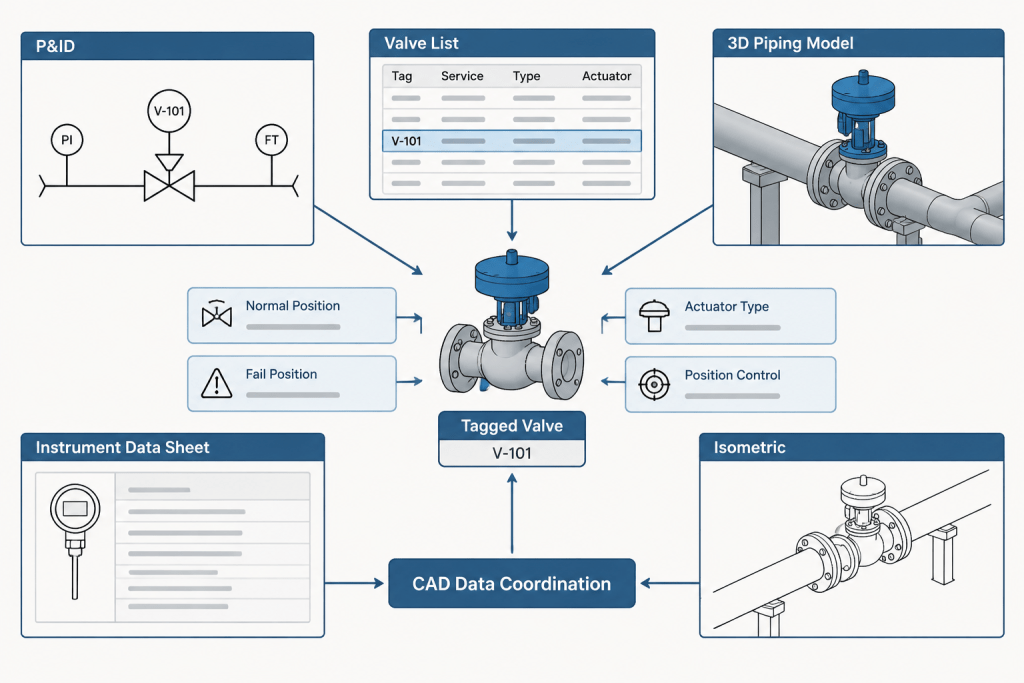
CAD metadata should use separate fields where the project data structure distinguishes valve normal position, fail position, actuator type, and control action. Combining all of these into one free-text field makes checking and data exchange more difficult.
Commanded Position Can Differ from Actual Position
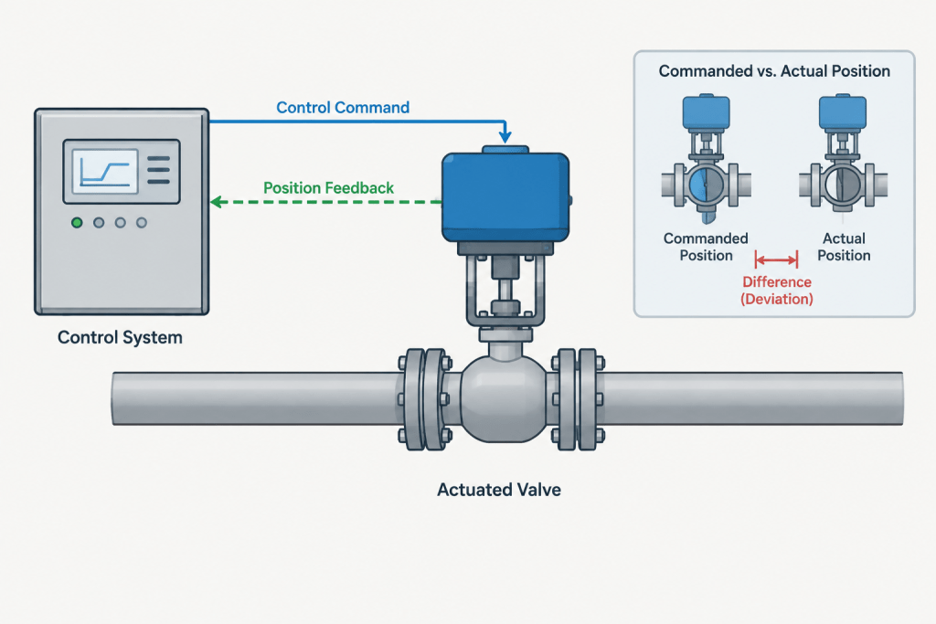
A control system can issue an open or close command without proving that the valve reached that position. Position switches, transmitters, or other feedback devices may be used to report actual status. During commissioning, a commanded-open valve might remain closed because of isolation, loss of utility, incorrect adjustment, mechanical binding, or incomplete wiring.
This distinction is important when preparing commissioning diagrams, control narratives, or model-based operational views. A static P&ID normally represents design intent rather than real-time status. Color-coding a drawing as though it showed live valve positions can be misleading unless the display is specifically connected to verified operational data.
How Valve State Should Appear in Project Documents
P&IDs
The P&ID commonly carries the valve tag, functional symbol, actuator indication, and selected operating or failure information according to the project legend. It is usually the primary graphical source for process function, but not every mechanical detail belongs there.
Valve Lists and Instrument Data
Structured lists can hold normal position, fail position, service, actuator information, control-system association, and other approved attributes. These lists are often better than crowded drawing notes for detailed state information.
3D Models and Piping Layouts
A 3D model should show the physical valve and actuator orientation needed for layout, access, and interference review. It may also store state attributes, but rotating a handwheel or actuator graphic does not reliably prove whether the process passage is open or closed. Many library components use simplified or fixed geometry.
Isometrics
Fabrication isometrics generally focus on construction, materials, connections, and component identification. Operational position notes should be included only when required by the project workflow. A normal-position label must not be mistaken for an instruction to fabricate or install an actuator in an arbitrary orientation.
A Practical CAD and Document-Checking Workflow
- Identify the authoritative source. Determine whether approved valve-state data comes from the P&ID, valve list, instrument index, control narrative, shutdown philosophy, or another controlled document.
- Separate the attributes. Maintain distinct fields for normal position, fail position, actuator information, and any lock or seal designation.
- Check the tag relationship. Confirm that the valve body, actuator, controls, and associated instruments are linked to the correct equipment or instrument tags.
- Review the failure basis. Do not record fail position without understanding which loss condition the designation addresses.
- Compare documents systematically. Look for conflicting abbreviations, blank fields, reversed open and closed states, and outdated revisions.
- Verify the legend. Abbreviations and symbol conventions can vary by owner or project. Use the applicable legend rather than relying on memory.
- Raise unresolved conflicts. Preserve the discrepancy in the review record and obtain discipline confirmation instead of making an undocumented CAD correction.
Common Drafting Errors
- Treating normally closed and fail closed as the same attribute.
- Assuming a manual valve has a fail position merely because it has a normal position.
- Reading valve state from the visual rotation of a generic CAD block.
- Using actuator spring direction as a substitute for verified assembly behavior.
- Copying an old P&ID note after the valve or control philosophy has changed.
- Placing conflicting state information on the P&ID, valve list, and model properties.
- Leaving the applicable failure condition undefined.
- Confusing process open or closed status with electrical contact terminology.
Why Clear State Terminology Matters
Valve-state data affects more than drawing appearance. It supports operating line-ups, control logic, shutdown review, commissioning, maintenance planning, and field verification. An apparently minor abbreviation can create a serious coordination problem if one discipline reads it as normal position while another reads it as failure response.
The safest drafting approach is to treat valve states as separate, controlled data items. Show only approved information, use the project legend, maintain consistency between documents, and never infer functional behavior solely from CAD geometry. A clear distinction among normal, fail, commanded, and actual states makes both drawings and data more dependable throughout the piping lifecycle.
Applying the Terminology During Design Reviews
A useful review method is to read every valve-state entry as a complete statement rather than as an isolated abbreviation. Identify the operating condition behind the normal position, the event behind the fail position, the source of any command, and the method used to confirm actual position. If one part of that statement is missing, the data may require clarification even when the open or closed designation appears clear.
Use Purpose-Specific Data Fields
Where the project database permits it, normal, fail, commanded, and actual states should remain separate attributes. Administrative controls, actuator details, and the applicable failure basis should also remain distinct from the process-state fields. This structure makes conflicts easier to detect and reduces the risk of exporting one meaning into a document that expects another.
Blank values also require controlled handling. A blank field might mean that the information is unknown, not applicable, awaiting approval, or simply omitted. Those meanings should not be treated as equivalent. Follow the project data convention and raise a query when the intended meaning cannot be established.
Check Context Before Reusing a Valve State
- Document context: Determine whether the entry describes design intent, an operating line-up, control logic, commissioning status, or a field observation.
- Operating context: Confirm which operating mode supports a normal-position designation.
- Failure context: Record the specific loss condition associated with the fail response.
- Revision context: Verify that the drawing and structured data reflect the same approved change.
- Feedback context: Distinguish a control command from positive indication that the valve reached the requested position.
Recommended Handoff Check
Before issuing coordinated CAD or engineering documents, compare the valve tag and state attributes across the controlled sources used by the project. Differences should be documented for discipline resolution rather than silently normalized by the drafter. This approach preserves traceability and prevents an apparently simple open or closed label from carrying the wrong operational meaning.
Frequently Asked Questions
Does normally open mean fail open?
No. Normally open describes an expected operating condition, while fail open describes the intended response to a defined failure. A valve can have different normal and fail positions.
Can a manual valve have a normal position?
Yes. A manual valve may have an approved normal operating position. That does not automatically give it a fail position, because fail terminology generally depends on a defined failure response and the valve assembly involved.
Why can commanded and actual positions disagree?
A command represents a request from a control or shutdown system. Actual position depends on physical valve movement and suitable feedback or field verification. Utility loss, isolation, adjustment, wiring, or mechanical conditions can prevent the requested movement.
Can valve position be determined from a CAD symbol or model?
Not reliably. Generic symbols and model components may use fixed or simplified geometry. Position data should come from approved project attributes, controlled documents, verified feedback, or field observation as appropriate.
What should a drafter do when the P&ID and valve list conflict?
Check document status, revisions, the project legend, and the designated authoritative source. Record the discrepancy and request discipline confirmation rather than choosing a position based on assumption.
Is fail in place an exact guarantee of valve position?
It expresses an intended response, but actual behavior depends on the complete valve and actuator arrangement and the failure being considered. The applicable project documentation should define the basis.