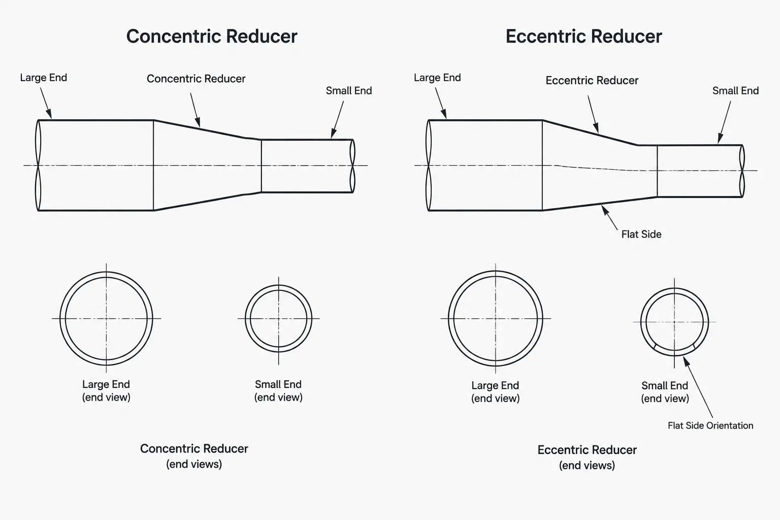
Choosing between concentric and eccentric pipe reducers is a geometry, process, and documentation decision. The fitting must connect the required pipe sizes while preserving the intended centerline, elevation, drainage path, and equipment approach. This guide explains how reducer type and orientation should be represented, checked, and communicated in CAD.
Concentric and eccentric reducers both connect pipe ends of different sizes, but they do not create the same centerline geometry. That difference affects routing, drainage, vapor collection, equipment connections, support elevations, and fabrication documentation. In CAD, selecting the correct reducer type is only the first step. The designer must also place and orient it according to the intended piping function.
A reducer should not be chosen only because it fits between two nominal pipe sizes. Its geometry must support the required flow path, preserve the intended pipe elevation, and match the project piping specification. Manufacturer or approved dimensional data must be used when the reducer’s end-to-end length, outside profile, or weld-end geometry affects the layout.
What is a concentric pipe reducer?
A concentric reducer transitions between two pipe sizes while keeping their centerlines aligned. Viewed from the end, the smaller opening is centered within the larger opening. In a straight run, the upstream and downstream pipe centerlines therefore remain collinear.
This symmetry makes concentric reducers straightforward to place and rotate in a CAD model. Rotation about the pipe axis generally does not change the connected centerlines or the reducer’s external envelope. The fitting still requires the correct size order, end connections, material specification, and dimensional record.
Concentric reducers are commonly considered where a centered transition is acceptable. They are often convenient in vertical piping because there is no preferred top or bottom orientation, although process behavior, solids handling, and equipment requirements must still be reviewed.
What is an eccentric pipe reducer?
An eccentric reducer transitions between different pipe sizes with their centerlines offset. One side of the transition is commonly described as the flat side, while the opposite side carries most of the change in diameter. The expression “flat side” is practical piping terminology; the exact manufactured profile should be taken from verified component data rather than inferred from a simplified CAD symbol.
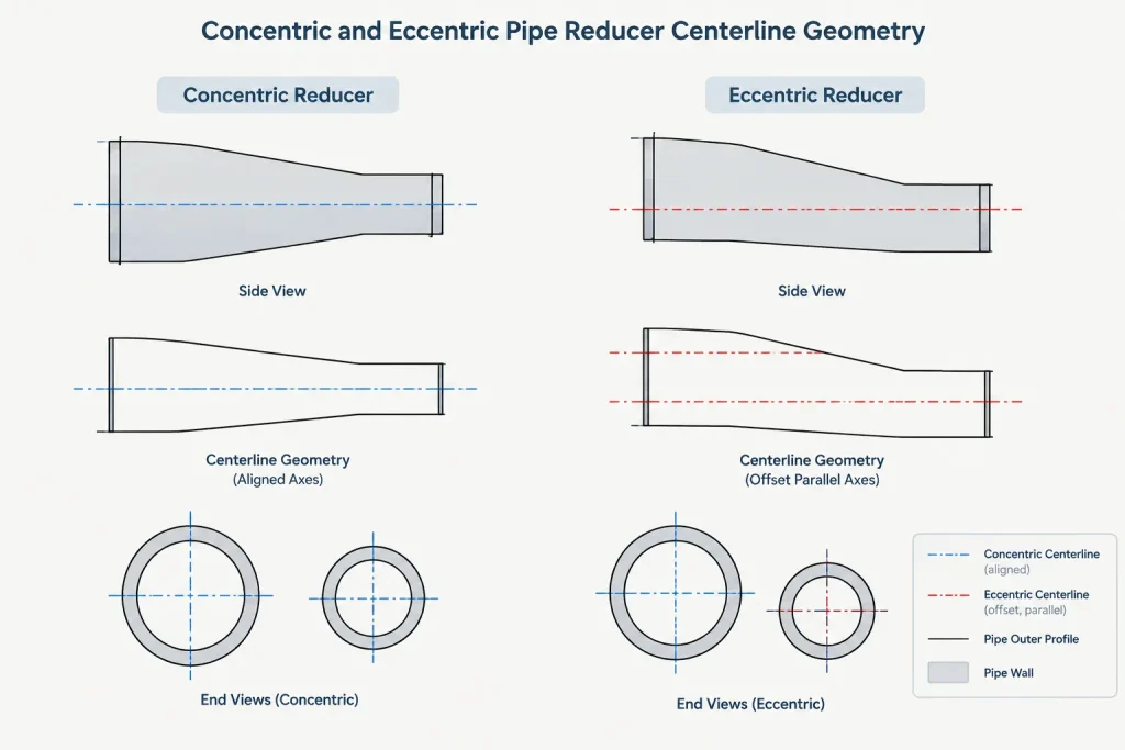
Unlike a concentric reducer, an eccentric reducer has a meaningful rotational orientation. Rotating it about its axis changes the direction of the centerline offset. The fitting can maintain a selected top, bottom, or side surface while moving the connected pipe centerline in another direction.
This makes eccentric reducers useful when the layout must control a high point, low point, pipe invert, top-of-pipe elevation, or equipment nozzle approach. It also means that a correctly sized but incorrectly rotated reducer can introduce an unintended pocket or elevation change.
Concentric vs. eccentric reducers at a glance
| Design issue | Concentric reducer | Eccentric reducer |
|---|---|---|
| Connected centerlines | Remain aligned | Are offset |
| Rotational orientation | Usually does not affect routing geometry | Controls the offset direction |
| Top or bottom continuity | Neither surface remains continuously aligned | A selected side can be maintained |
| Potential pocket behavior | May create a local high or low region in a horizontal transition | Can be oriented to manage a high or low point |
| CAD data required | Sizes, end type, length, specification, ports | The same data plus offset direction or clocking |
| Common drafting risk | Using an assumed generic length | Correct fitting type placed at the wrong rotation |
Flat on top and flat on bottom terminology
Two common eccentric-reducer callouts are flat on top and flat on bottom. They describe the reducer’s installed orientation relative to the project’s vertical reference, not merely how the fitting happens to appear on a drawing sheet.
- Flat on top: The upper side of the transition is maintained, with the centerline offset occurring toward the lower side.
- Flat on bottom: The lower side is maintained, with the centerline offset occurring toward the upper side.
- Flat on side: The eccentricity is rotated laterally, often to satisfy a nozzle, wall, rack, or clearance condition.
Abbreviations can vary between companies and projects. If a drawing uses an abbreviated orientation note, the drawing legend or project drafting practice should define it. A clear graphical representation is valuable because a text note can be separated from the fitting during drawing revisions.
Flow behavior and pocket control
Reducer orientation is often associated with avoiding trapped gas or retained liquid. In a horizontal liquid line, a local high region may collect vapor or air. A local low region may retain liquid, sediment, or condensate. The preferred arrangement depends on the service, flow direction, operating state, cleaning method, and drainage or venting strategy.
For example, an eccentric reducer installed near a pump suction is often arranged to avoid creating a vapor pocket in the approach piping. However, this common practice should not be treated as a universal CAD rule. Pump configuration, suction direction, piping slope, nozzle orientation, vendor requirements, and project criteria must be checked together.

Likewise, flat-on-bottom orientation may help preserve a low flow line or invert in some services, but it can be inappropriate where the transition would create an unwanted high point. Reducer orientation should express the hydraulic and operational intent rather than follow a memorized note without context.
Using outside diameter to understand the offset
The offset of an eccentric reducer is related to the difference between the outside radii at its two ends. Conceptually, when one external side is aligned, the centerline shift corresponds to half the difference between the connected outside diameters. Nominal pipe size labels alone are not suitable for calculating this geometry because they are not literal measured diameters.
This relationship is useful as a CAD reasonableness check, but it is not a replacement for approved fitting dimensions. Actual component geometry may include end preparations, straight portions, forming transitions, tolerances, or manufacturer-specific details that are absent from a simplified model.
CAD placement and port setup
A reliable reducer component should have connection ports at the actual end-face centers. Each port should carry the correct nominal size and connection type. For a concentric reducer, both ports share one axis. For an eccentric reducer, the port axes are parallel but offset.
The component origin should support predictable placement and replacement. Common strategies include locating the origin at one end-face center or at a defined fitting reference point. Whichever method is used, the library convention should remain consistent so that changing reducer sizes does not unexpectedly move an equipment nozzle or a controlled pipe endpoint.
Checks after inserting an eccentric reducer
- Confirm the large-end and small-end size order.
- Verify that both ports connect without a hidden centerline discontinuity.
- Rotate the fitting to the intended top, bottom, or side orientation.
- Check the resulting downstream centerline elevation or lateral position.
- Review the transition for gas, liquid, or solids pockets.
- Confirm that the fitting length comes from the applicable project data source.
- Check insulation, supports, nearby steel, and maintenance access against the actual envelope.
Dimensioning reducers on drawings
A piping drawing should control the location needed for fabrication and installation without creating conflicting dimensions. If the reducer lies between two fixed endpoints, the fitting’s verified end-to-end dimension contributes to the pipe cut-length calculation. A generic symbol should not be stretched to fill the available space while retaining an unrelated catalog identity.

For eccentric reducers, dimensions may need to control both axial placement and the resulting centerline offset. Elevation callouts should clearly state whether they refer to pipe centerline, top of pipe, bottom of pipe, or another project datum. Mixing these references can make a correctly modeled reducer appear incorrect during drawing review.
On an isometric, the reducer symbol and orientation note should agree with the reported elevations. On plans and sections, include the view that best communicates the eccentricity. A reducer that looks concentric in one projection may be visibly eccentric in another.
Bills of material and fabrication communication
The bill of material should distinguish concentric from eccentric reducers and identify the connected sizes in the project’s required order. It should also carry the appropriate material, wall designation, end type, and piping specification information. Orientation is normally an installation or spool-geometry property rather than a different purchased size, but it still needs to be communicated on fabrication drawings.
Do not rely on the bill of material alone to tell the shop how to rotate an eccentric reducer. Show the orientation through the isometric geometry, elevations, clocking information, or an unambiguous note. If the reducer is welded into a spool, its rotation should be treated as a controlled fabrication condition.
A practical selection workflow
- Establish the required end sizes and connections. Confirm the piping specification before choosing a component.
- Identify the controlling line. Decide whether centerline, top, bottom, invert, or a side clearance must remain aligned.
- Review process behavior. Consider gas collection, drainage, sediment, cleaning, and flow direction.
- Check equipment interfaces. Verify nozzle position, vendor requirements, and the available straight approach.
- Select concentric or eccentric geometry. Do not use rotation or scaling to imitate the other type.
- Apply the intended orientation. Record flat-on-top, flat-on-bottom, or lateral clocking where needed.
- Validate dimensions and documentation. Reconcile the model, isometric, elevations, and bill of material.
The central distinction between concentric and eccentric pipe reducers is not simply their external shape. A concentric reducer preserves a common axis, while an eccentric reducer deliberately moves that axis to control another part of the piping geometry. Accurate CAD work must capture that functional difference, use verified component dimensions, and communicate orientation clearly enough for fabrication and installation.
Reducer model review and revision control
Reducer orientation should remain traceable as the model develops. A replacement fitting, revised pipe size, moved nozzle, or changed routing elevation can alter the intended transition even when the line still appears connected. After a revision, review the reducer as a functional component rather than relying only on connectivity or clash status.
Information worth retaining in the CAD record
- Reducer type, connected size order, end connections, and applicable piping specification.
- Verified dimensional source used for the component geometry.
- Port locations and the direction of the eccentric offset.
- The controlled reference, such as centerline, top of pipe, bottom of pipe, or lateral alignment.
- Orientation notes or clocking data needed by drawing and fabrication workflows.
Automated routing tools may confirm that ports connect without confirming that an eccentric reducer faces the intended direction. Visual review should therefore include a view that exposes the offset, along with the elevations or datums that define the design intent.
Coordination across model outputs
The model, isometric, orthographic views, material report, and fabrication information should describe the same reducer. If one output identifies an eccentric fitting while another graphic implies a concentric transition, the discrepancy should be resolved before release. The same review applies when a reducer is mirrored, copied to a line with a different flow condition, or replaced from a component catalog.
Final suitability depends on the project piping specification, process requirements, equipment information, approved component data, and fabrication practices. A visually plausible CAD arrangement is not a substitute for those controls.
Frequently asked questions
Can an eccentric reducer be rotated to any orientation?
It can be rotated around the pipe axis in a CAD model, but the selected orientation must match the required top, bottom, or side alignment. Rotation changes the direction of the centerline offset and may change pocket behavior, elevations, and clearances.
Why can an eccentric reducer look concentric in a drawing?
A projection viewed parallel to the offset direction may hide the eccentricity. Use a section, elevation, alternate view, orientation note, or clear clocking information to communicate the actual installation.
Should flow direction alone determine reducer orientation?
No. Flow direction is only part of the review. Service behavior, drainage, venting, solids, piping slope, equipment configuration, nozzle position, and project requirements can all influence the preferred orientation.
Can nominal pipe size be used to calculate the eccentric offset?
Nominal size labels are not literal outside diameters. Outside-diameter information can support a geometry check, but approved fitting data should control the modeled component and fabrication dimensions.
What should be checked after replacing a reducer in CAD?
Reconfirm the size order, fitting type, port locations, end-to-end geometry, offset direction, controlled elevation, nearby clearances, and drawing annotations. Also verify that reports and fabrication outputs still identify the intended component.
Is a flat-side note enough for fabrication?
The note should be consistent with the displayed spool geometry, elevations, and project drafting convention. When the orientation could be misread, add a view or clocking reference that makes the required rotation unambiguous.