Tag: piping CAD

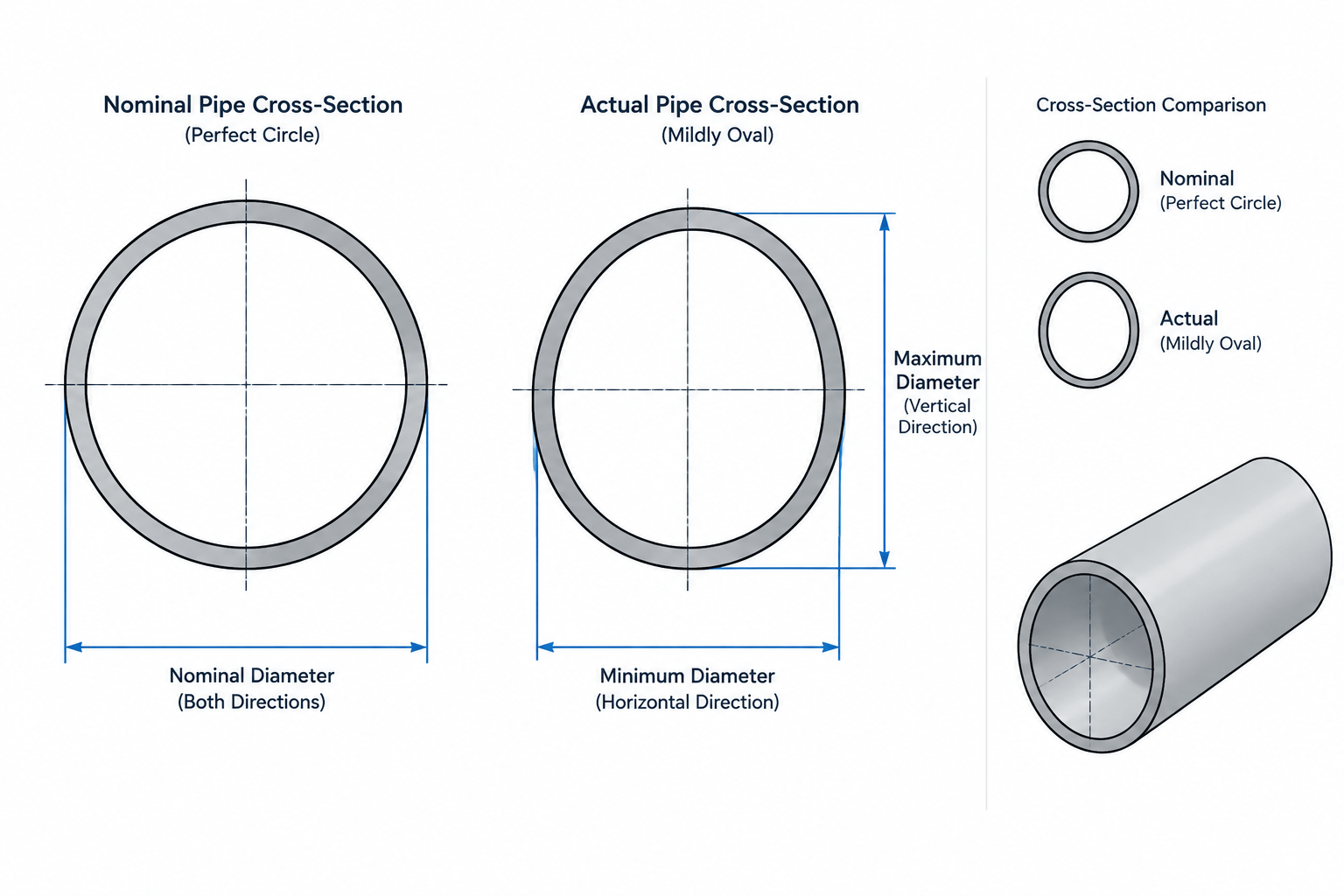
  • Pipe Ovality and Out-of-Roundness: What CAD Models Do Not Show

    Pipe Ovality and Out-of-Roundness: What CAD Models Do Not Show

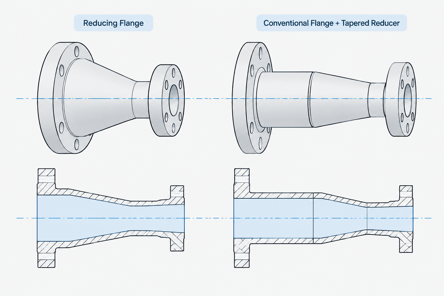
  • Reducing Flanges vs. Reducer-and-Flange Assemblies in Piping CAD

    Reducing Flanges vs. Reducer-and-Flange Assemblies in Piping CAD

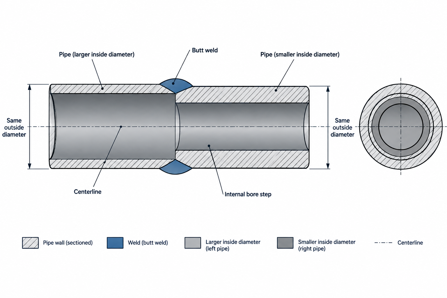
  • Pipe Bore Mismatch at Butt-Weld Connections: A Practical CAD and Detailing Guide

    Pipe Bore Mismatch at Butt-Weld Connections: A Practical CAD and Detailing Guide

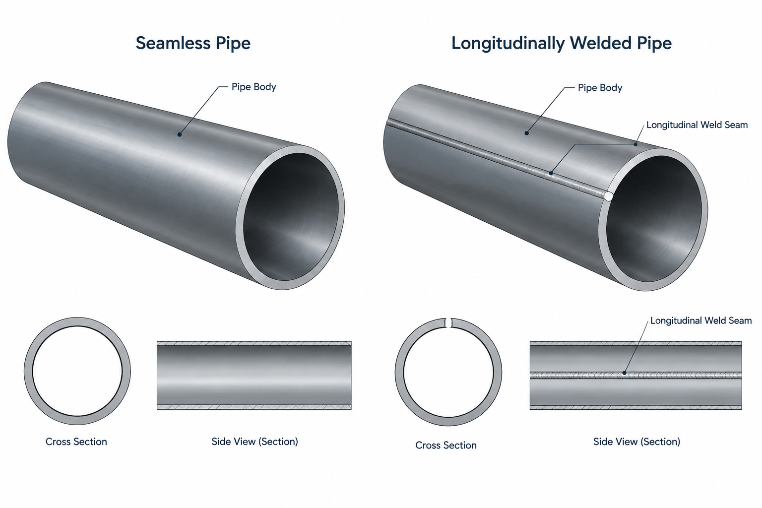
  • Seamless vs. Welded Pipe in CAD and Piping Documentation

    Seamless vs. Welded Pipe in CAD and Piping Documentation

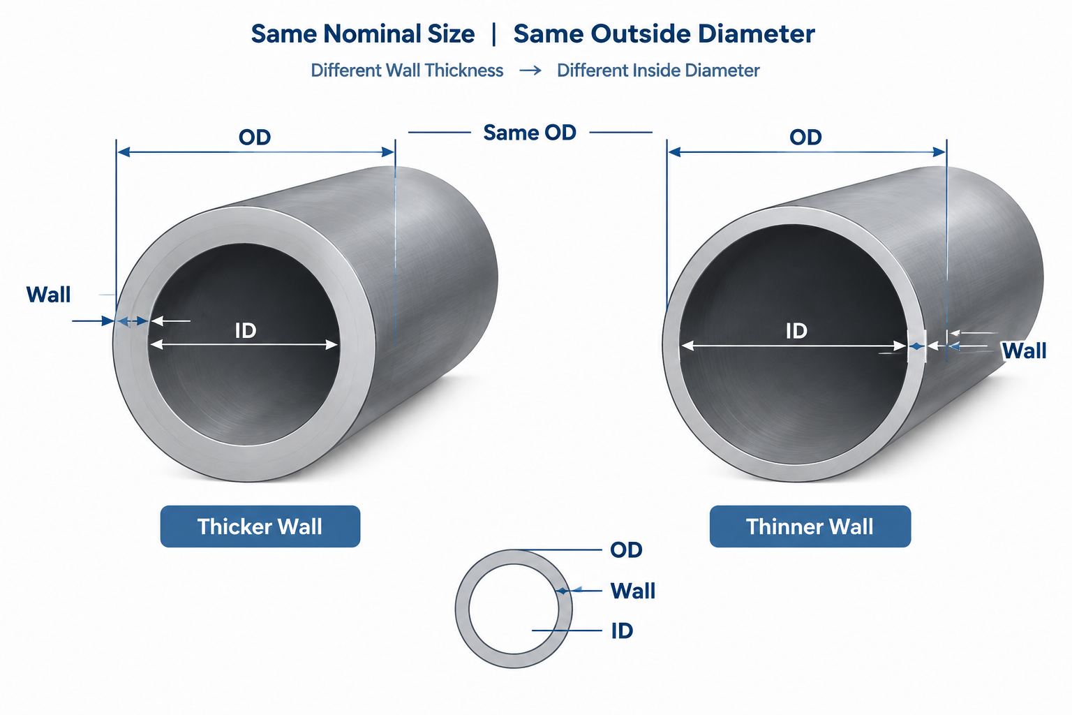
  • Why Pipe Outside Diameter Usually Stays the Same When Schedule Changes

    Why Pipe Outside Diameter Usually Stays the Same When Schedule Changes

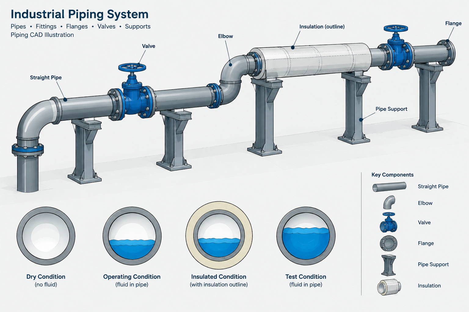
  • Piping Weight Data in CAD: Dry, Operating, Test, and Insulated Loads

    Piping Weight Data in CAD: Dry, Operating, Test, and Insulated Loads

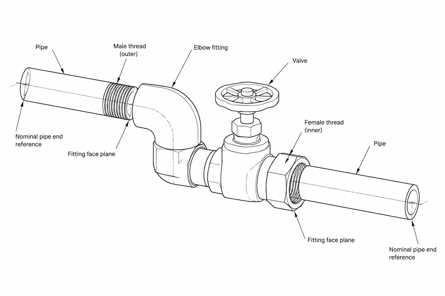
  • Threaded Pipe Connections in CAD: Engagement, Makeup, and Cut-Length Control

    Threaded Pipe Connections in CAD: Engagement, Makeup, and Cut-Length Control

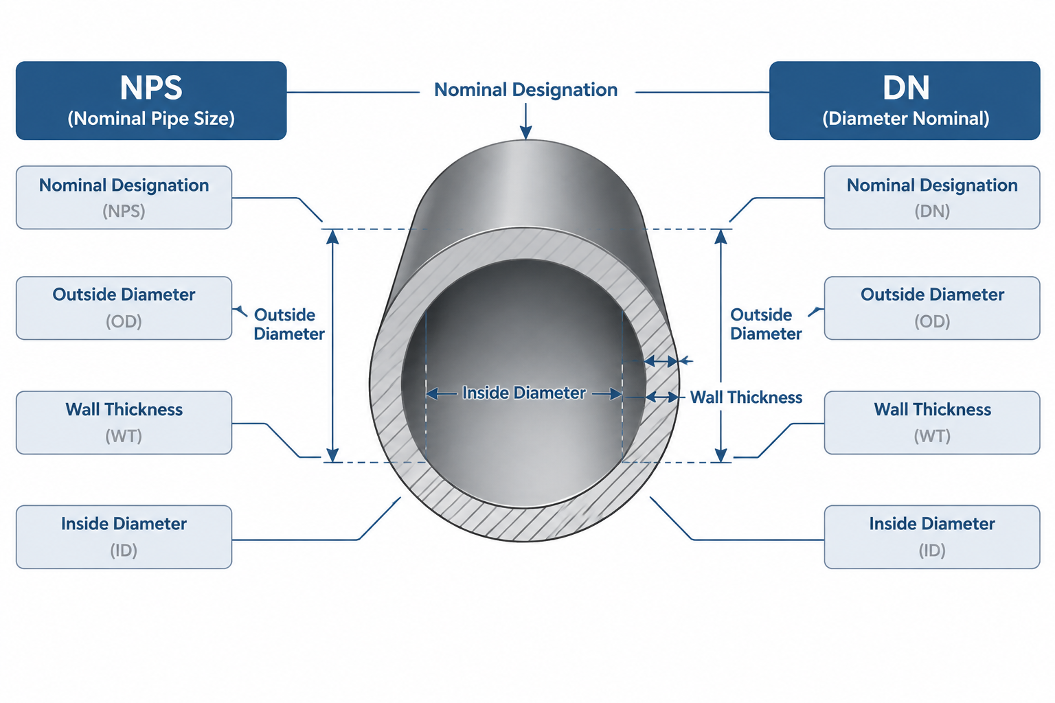
  • NPS vs. DN: Why Nominal Pipe Sizes Are Not Direct Unit Conversions

    NPS vs. DN: Why Nominal Pipe Sizes Are Not Direct Unit Conversions

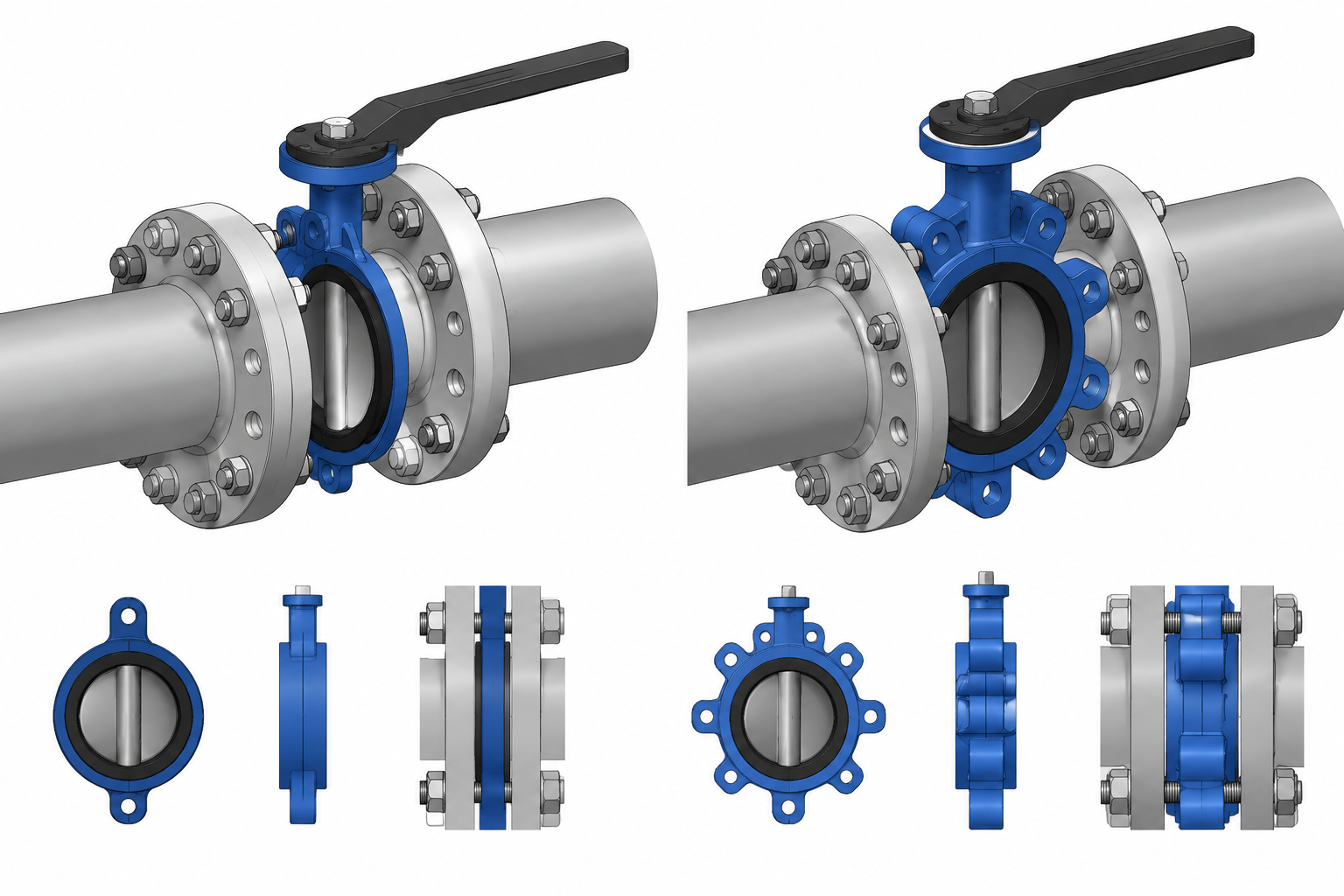
  • Wafer vs. Lug Butterfly Valves in Piping CAD: Connections, Bolting, and Maintenance

    Wafer vs. Lug Butterfly Valves in Piping CAD: Connections, Bolting, and Maintenance