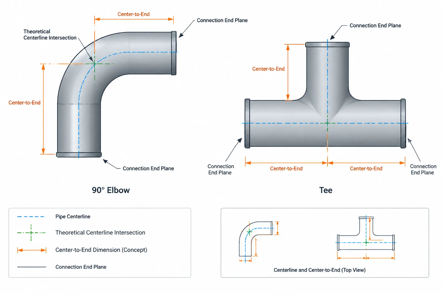
Tag: piping CAD

  • Pipe Fitting Center-to-End Dimensions: How to Read and Use Them in CAD

    Pipe Fitting Center-to-End Dimensions: How to Read and Use Them in CAD

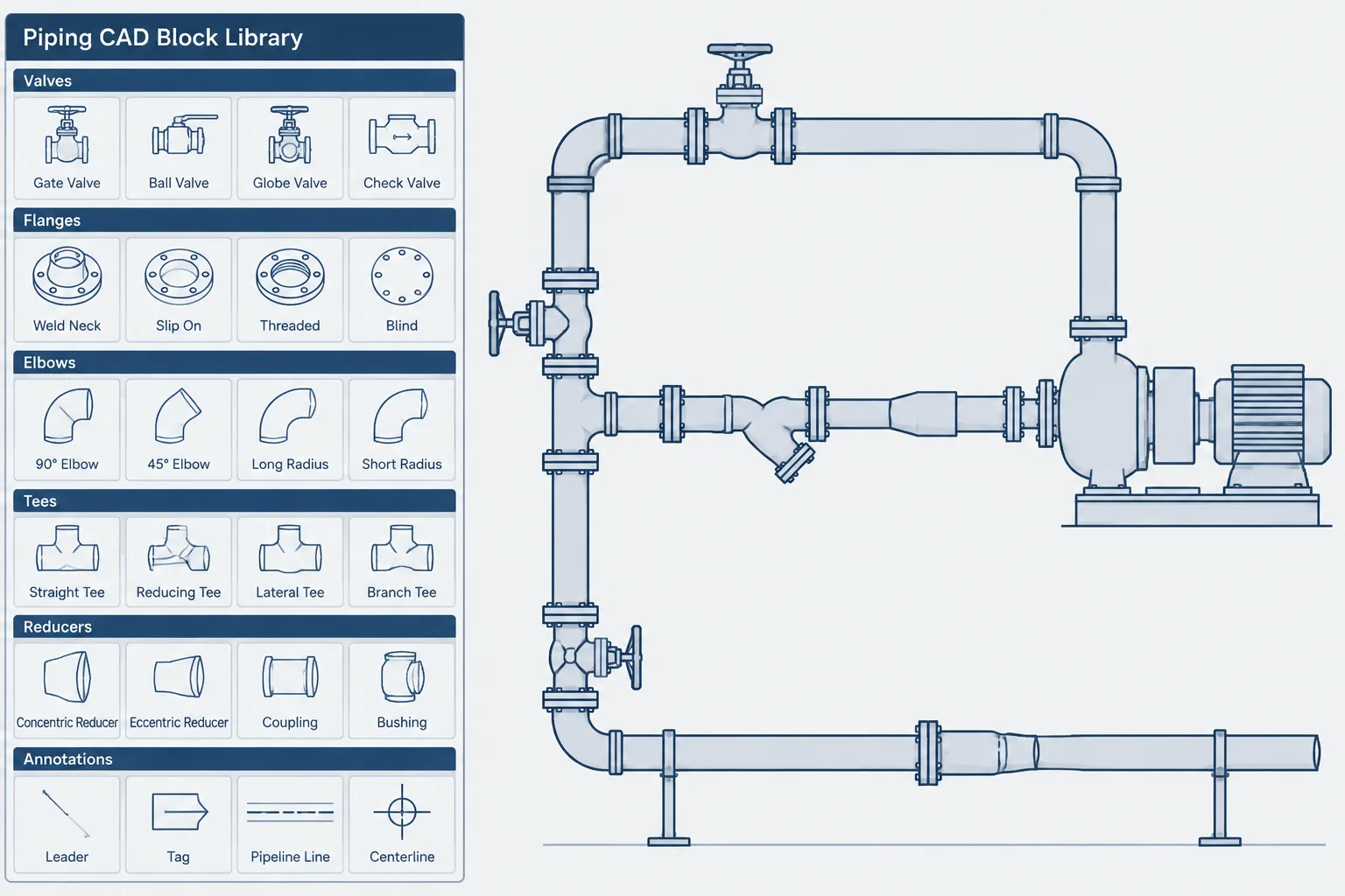
  • Piping CAD Block Library Management: A Practical Workflow for Reuse and Control

    Piping CAD Block Library Management: A Practical Workflow for Reuse and Control

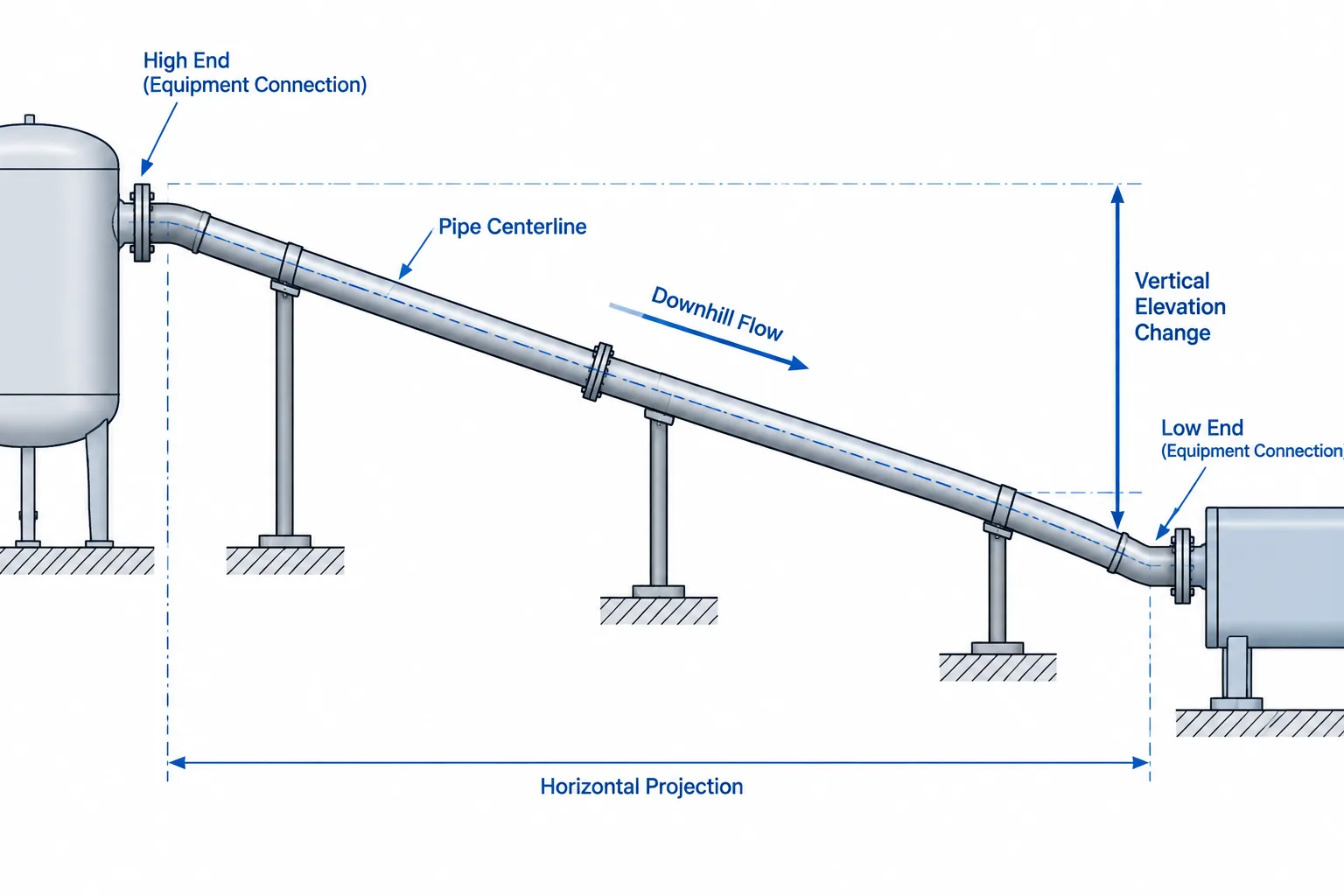
  • Piping Slope in CAD: Grade Notation, Elevation Control, and Model Checks

    Piping Slope in CAD: Grade Notation, Elevation Control, and Model Checks

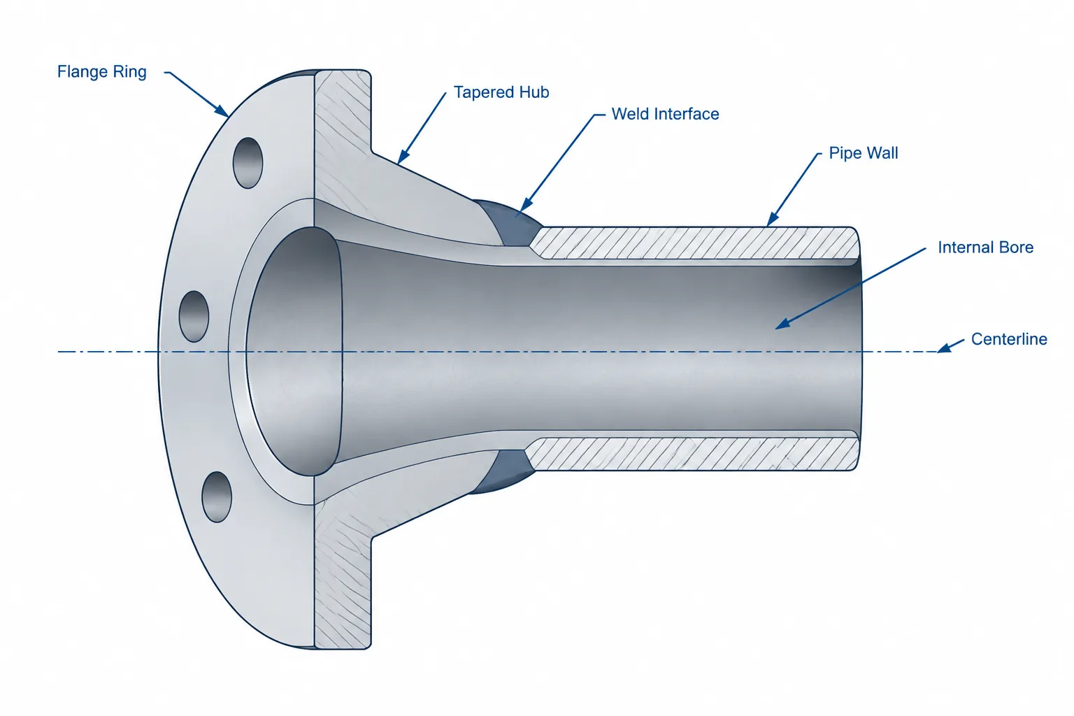
  • Weld Neck Flange Bore in CAD: Matching the Hub, Pipe Wall, and Weld Detail

    Weld Neck Flange Bore in CAD: Matching the Hub, Pipe Wall, and Weld Detail

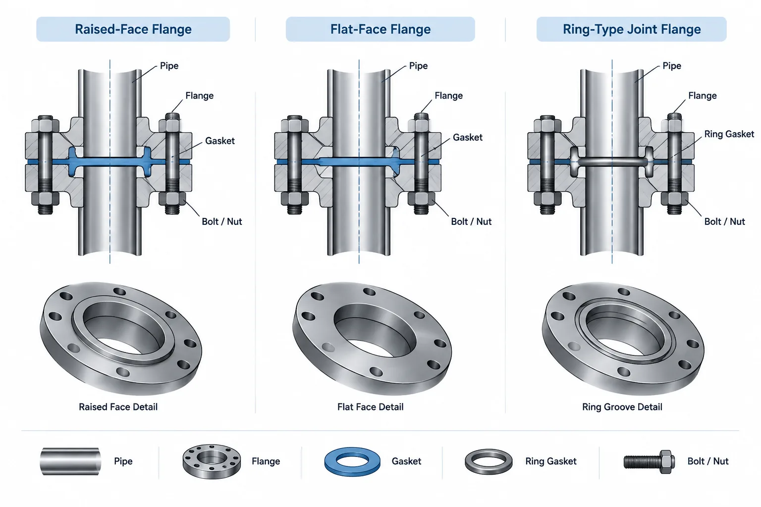
  • Flange Face Types in Piping CAD: Raised Face, Flat Face, and Ring-Type Joint

    Flange Face Types in Piping CAD: Raised Face, Flat Face, and Ring-Type Joint

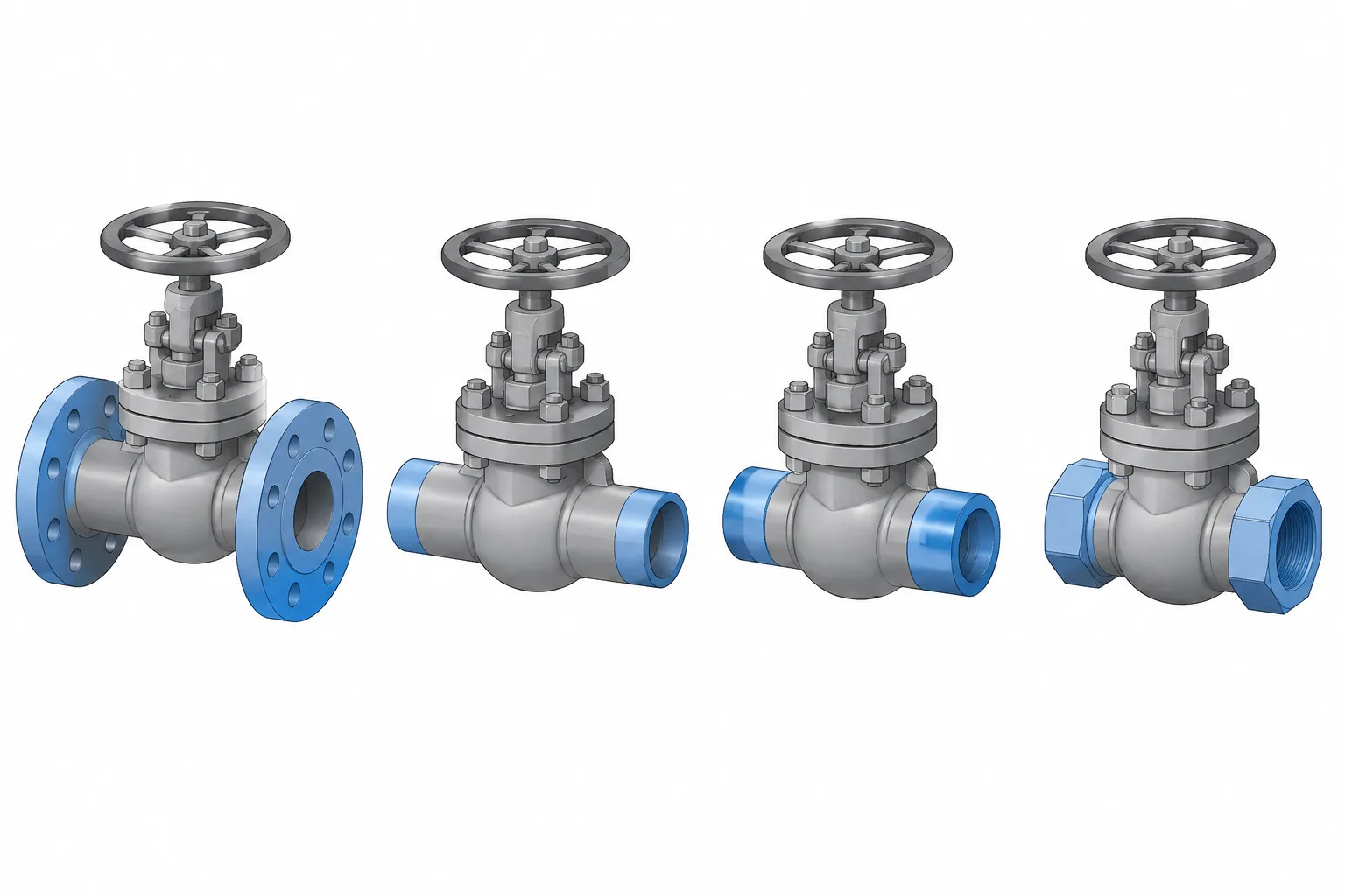
  • Valve End Connections in Piping CAD: Flanged, Butt-Weld, Socket-Weld, and Threaded

    Valve End Connections in Piping CAD: Flanged, Butt-Weld, Socket-Weld, and Threaded

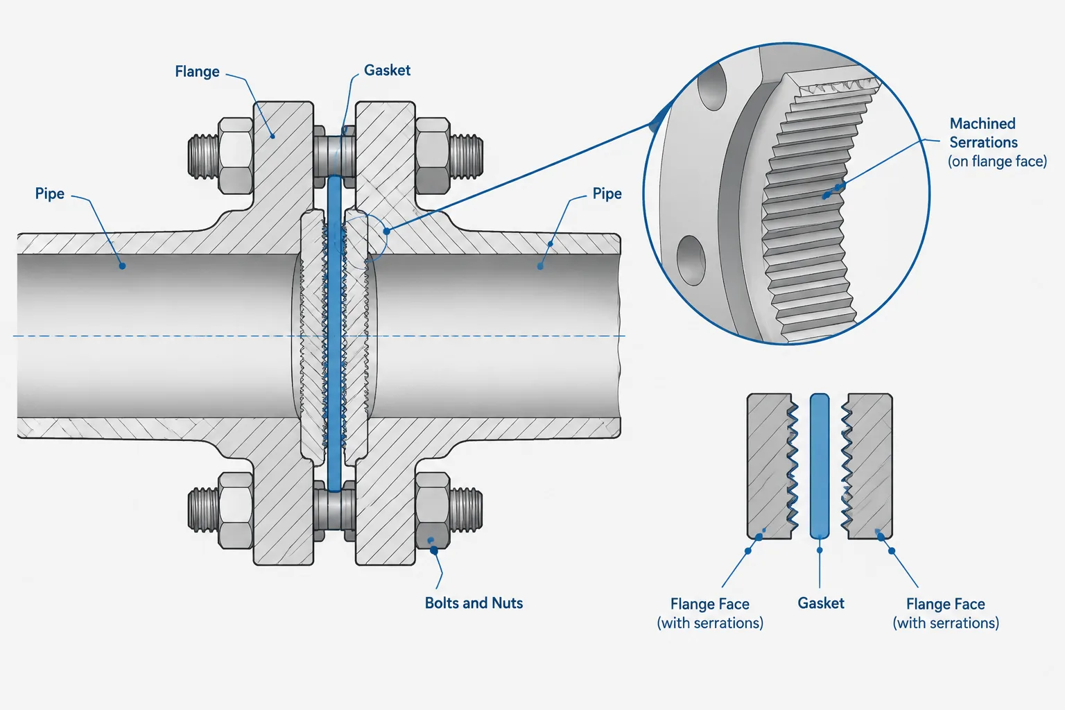
  • Flange Facing Finish in Piping Drawings: Serrations, Roughness, and Gasket Compatibility

    Flange Facing Finish in Piping Drawings: Serrations, Roughness, and Gasket Compatibility

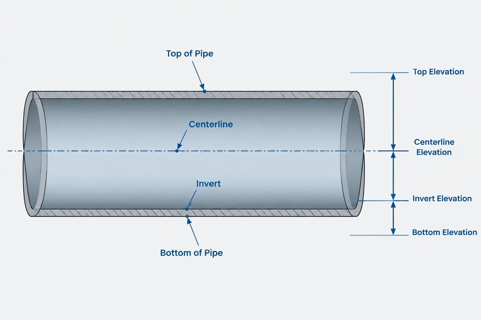
  • Pipe Elevation Notation in CAD: Centerline, BOP, TOP, and Invert Explained

    Pipe Elevation Notation in CAD: Centerline, BOP, TOP, and Invert Explained

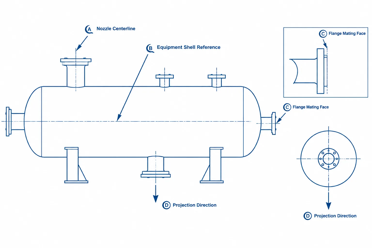
  • Equipment Nozzle Projection in Piping CAD: Reference Points, Flange Faces, and Interface Control

    Equipment Nozzle Projection in Piping CAD: Reference Points, Flange Faces, and Interface Control